Cirkit Designer Logo
Cirkit Designer
Your all-in-one circuit design IDE
Home / 
Component Documentation

How to Use 776273-1: Examples, Pinouts, and Specs

Image of 776273-1
Cirkit Designer LogoDesign with 776273-1 in Cirkit Designer

Introduction

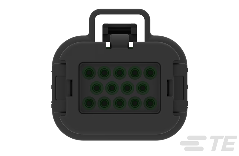
The 776273-1 is a 14-position housing connector manufactured by TE Connectivity. It is designed to house female terminals, providing a secure and reliable connection for wires or cables in electronic systems. This component is widely used in applications requiring robust and durable interconnections, such as automotive systems, industrial equipment, and consumer electronics.

Explore Projects Built with 776273-1

Use Cirkit Designer to design, explore, and prototype these projects online. Some projects support real-time simulation. Click "Open Project" to start designing instantly!
Battery-Powered Emergency Alert System with NUCLEO-F072RB, SIM800L, and GPS NEO 6M
Image of women safety: A project utilizing 776273-1 in a practical application
This circuit is an emergency alert system that uses a NUCLEO-F072RB microcontroller to send SMS alerts and make calls via a SIM800L GSM module, while obtaining location data from a GPS NEO 6M module. The system is powered by a Li-ion battery and includes a TP4056 module for battery charging and protection, with a rocker switch to control power to the microcontroller.
Cirkit Designer LogoOpen Project in Cirkit Designer
Stepper Motor Control System with SIMATIC S7-300 and TB6600 Driver
Image of Copy of PLC-Based Step Motor Speed and Direction Control System: A project utilizing 776273-1 in a practical application
This circuit controls a stepper motor using a tb6600 micro stepping motor driver and a DKC-1A stepper motor controller. The system is powered through panel mount banana sockets and includes a relay module for additional control, interfaced with a SIMATIC S7-300 PLC for automation.
Cirkit Designer LogoOpen Project in Cirkit Designer
IR Obstacle Detection System with Relay-Controlled Gearmotors and Boost Converters
Image of LFR 1: A project utilizing 776273-1 in a practical application
This circuit consists of two FC-51 IR Obstacle Sensors connected to two KF-301 relays, which likely serve as triggers for switching the relays. Four gearmotors are powered through two XL6009E1 Boost Converters, which are likely used to step up the voltage from a 2-cell 18650 Li-ion battery pack. The relays appear to control the power flow to the boost converters, and thus to the gearmotors, based on the obstacle detection inputs.
Cirkit Designer LogoOpen Project in Cirkit Designer
Sound and Motion-Activated Switching Circuit with 4017 Decade Counter and BC547 Transistors
Image of m.s: A project utilizing 776273-1 in a practical application
This circuit is a sequential control system with a 4017 decade counter at its core, driving relays through transistors based on its output states. It includes toggle switches and a PIR sensor for triggering events, a condenser microphone for sound detection, and an LED for visual indication. The circuit operates without a microcontroller, relying on the counter's sequence and external inputs to control the connected loads.
Cirkit Designer LogoOpen Project in Cirkit Designer

Explore Projects Built with 776273-1

Use Cirkit Designer to design, explore, and prototype these projects online. Some projects support real-time simulation. Click "Open Project" to start designing instantly!
Image of women safety: A project utilizing 776273-1 in a practical application
Battery-Powered Emergency Alert System with NUCLEO-F072RB, SIM800L, and GPS NEO 6M
This circuit is an emergency alert system that uses a NUCLEO-F072RB microcontroller to send SMS alerts and make calls via a SIM800L GSM module, while obtaining location data from a GPS NEO 6M module. The system is powered by a Li-ion battery and includes a TP4056 module for battery charging and protection, with a rocker switch to control power to the microcontroller.
Cirkit Designer LogoOpen Project in Cirkit Designer
Image of Copy of PLC-Based Step Motor Speed and Direction Control System: A project utilizing 776273-1 in a practical application
Stepper Motor Control System with SIMATIC S7-300 and TB6600 Driver
This circuit controls a stepper motor using a tb6600 micro stepping motor driver and a DKC-1A stepper motor controller. The system is powered through panel mount banana sockets and includes a relay module for additional control, interfaced with a SIMATIC S7-300 PLC for automation.
Cirkit Designer LogoOpen Project in Cirkit Designer
Image of LFR 1: A project utilizing 776273-1 in a practical application
IR Obstacle Detection System with Relay-Controlled Gearmotors and Boost Converters
This circuit consists of two FC-51 IR Obstacle Sensors connected to two KF-301 relays, which likely serve as triggers for switching the relays. Four gearmotors are powered through two XL6009E1 Boost Converters, which are likely used to step up the voltage from a 2-cell 18650 Li-ion battery pack. The relays appear to control the power flow to the boost converters, and thus to the gearmotors, based on the obstacle detection inputs.
Cirkit Designer LogoOpen Project in Cirkit Designer
Image of m.s: A project utilizing 776273-1 in a practical application
Sound and Motion-Activated Switching Circuit with 4017 Decade Counter and BC547 Transistors
This circuit is a sequential control system with a 4017 decade counter at its core, driving relays through transistors based on its output states. It includes toggle switches and a PIR sensor for triggering events, a condenser microphone for sound detection, and an LED for visual indication. The circuit operates without a microcontroller, relying on the counter's sequence and external inputs to control the connected loads.
Cirkit Designer LogoOpen Project in Cirkit Designer

Common Applications

  • Automotive wiring harnesses
  • Industrial control systems
  • Consumer electronics
  • Communication equipment
  • Power distribution systems

Technical Specifications

The following table outlines the key technical details of the 776273-1 connector:

Parameter Specification
Manufacturer TE Connectivity
Part Number 776273-1
Number of Positions 14
Terminal Type Female
Housing Material Nylon (Polyamide), UL 94V-0 rated
Operating Temperature -30°C to +105°C
Voltage Rating 250V (maximum)
Current Rating 7A (maximum per contact)
Mounting Style Free-hanging or panel mount
Mating Connector Compatible with TE male terminal housings

Pin Configuration and Descriptions

The 776273-1 housing does not have electrical pins itself but is designed to hold 14 female terminals. The terminals are inserted into the housing and correspond to the following layout:

Position Description
1-14 Slots for female terminals

Each position is numbered for easy identification, ensuring proper wiring and connection.

Usage Instructions

How to Use the 776273-1 in a Circuit

  1. Prepare the Wires: Strip the insulation from the wires to expose the appropriate length of conductor for crimping.
  2. Crimp the Terminals: Use a compatible crimping tool to attach female terminals to the stripped wire ends. Ensure a secure and reliable crimp.
  3. Insert Terminals into the Housing: Push the crimped terminals into the corresponding slots in the 776273-1 housing until they click into place. Verify that each terminal is securely locked.
  4. Connect to Mating Connector: Align the 776273-1 housing with the corresponding male connector and push them together until fully mated.

Important Considerations and Best Practices

  • Wire Gauge Compatibility: Ensure the wire gauge matches the terminal specifications to avoid loose connections or damage.
  • Crimping Tool: Use the recommended crimping tool for TE female terminals to achieve optimal results.
  • Insertion Force: Do not use excessive force when inserting terminals into the housing to prevent damage.
  • Environmental Conditions: Ensure the operating environment does not exceed the specified temperature or voltage ratings.

Example: Using the 776273-1 with an Arduino UNO

While the 776273-1 is not directly connected to an Arduino UNO, it can be used to organize and secure wires in a project. For example, you can use it to connect multiple sensors or actuators to the Arduino via a custom wiring harness.

// Example: Reading multiple sensors connected via a 776273-1 housing
// This code assumes sensors are connected to analog pins A0 to A3.

void setup() {
  Serial.begin(9600); // Initialize serial communication
}

void loop() {
  // Read sensor values
  int sensor1 = analogRead(A0); // Sensor connected to A0
  int sensor2 = analogRead(A1); // Sensor connected to A1
  int sensor3 = analogRead(A2); // Sensor connected to A2
  int sensor4 = analogRead(A3); // Sensor connected to A3

  // Print sensor values to the Serial Monitor
  Serial.print("Sensor 1: ");
  Serial.println(sensor1);
  Serial.print("Sensor 2: ");
  Serial.println(sensor2);
  Serial.print("Sensor 3: ");
  Serial.println(sensor3);
  Serial.print("Sensor 4: ");
  Serial.println(sensor4);

  delay(1000); // Wait 1 second before the next reading
}

Troubleshooting and FAQs

Common Issues

  1. Terminals Not Locking into Place

    • Cause: Incorrect terminal size or improper insertion.
    • Solution: Verify that the terminals are compatible with the housing and ensure they are fully inserted until they click.
  2. Loose Connections

    • Cause: Poor crimping or mismatched wire gauge.
    • Solution: Use the recommended crimping tool and ensure the wire gauge matches the terminal specifications.
  3. Difficulty Mating Connectors

    • Cause: Misalignment or debris in the connectors.
    • Solution: Align the connectors carefully and inspect for any obstructions before mating.
  4. Overheating

    • Cause: Exceeding the current or voltage rating.
    • Solution: Ensure the circuit operates within the specified ratings of the connector.

FAQs

Q: Can the 776273-1 be used in outdoor applications?
A: The housing is not specifically rated for outdoor use. If used outdoors, ensure it is protected from moisture and extreme environmental conditions.

Q: What is the recommended wire gauge for this connector?
A: The recommended wire gauge depends on the terminals used, typically ranging from 18 AWG to 24 AWG.

Q: How do I remove a terminal from the housing?
A: Use a terminal extraction tool to release the locking mechanism and gently pull the terminal out of the housing.

Q: Is the housing reusable?
A: Yes, the housing can be reused if the terminals are removed without damage. However, ensure the terminals are in good condition before reinserting them.