Cirkit Designer
Your all-in-one circuit design IDE
Home /
Component Documentation
How to Use Test 2: Examples, Pinouts, and Specs
Introduction
- Test 2 is a placeholder electronic component commonly used in circuit simulations or educational environments. It is designed to verify the functionality of circuits without introducing specific electrical characteristics. This component is ideal for testing purposes and serves as a generic substitute in various applications.
- Common Applications:
- Circuit design and simulation
- Educational demonstrations
- Prototyping and testing circuit layouts
Explore Projects Built with Test 2
Arduino Mega 2560-Based Soil Nutrient Testing System with Bluetooth and LCD Display
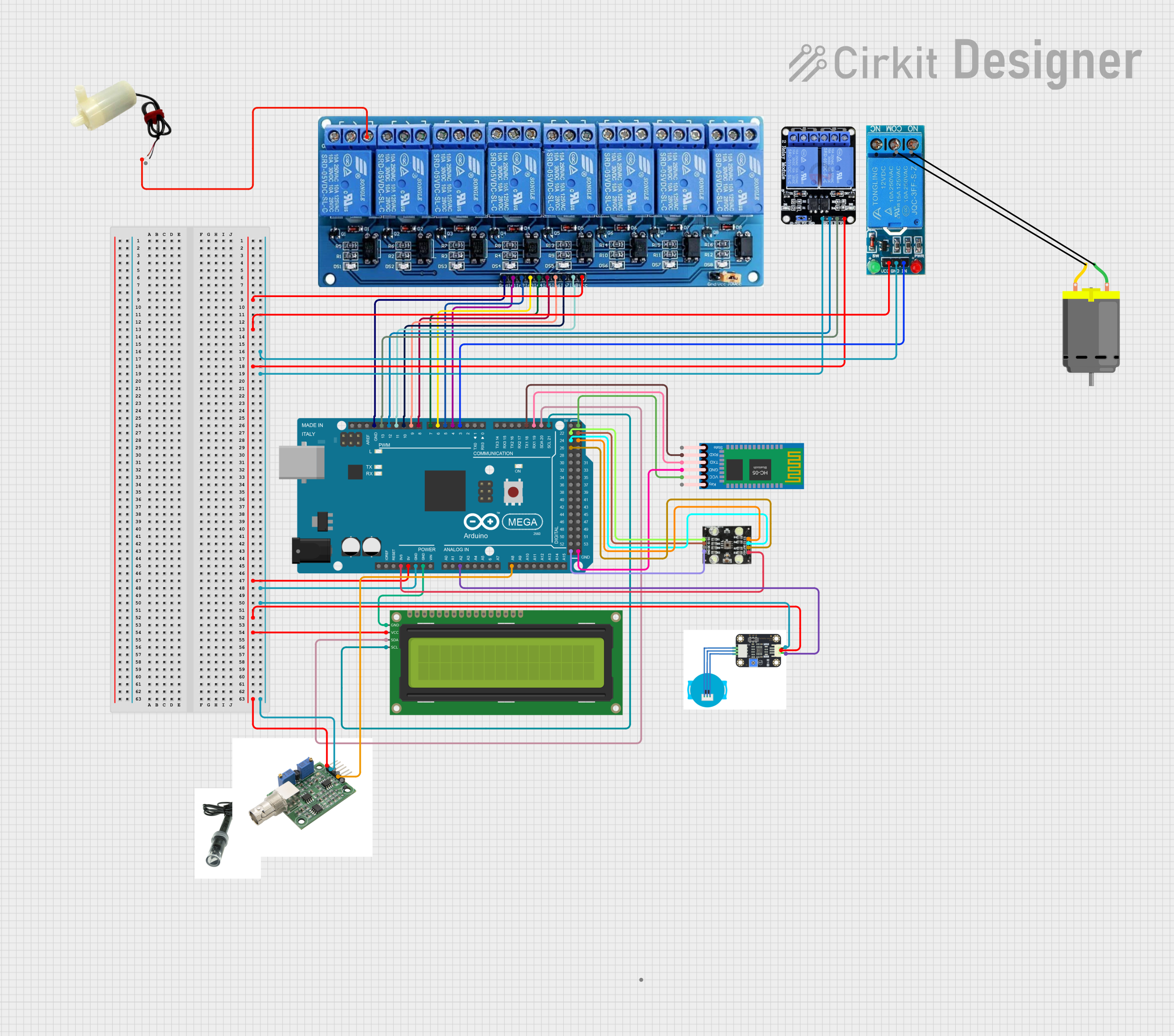
This circuit is an automated chemical testing system controlled by an Arduino Mega 2560. It uses various sensors, including a turbidity sensor and a color sensor, to measure water quality parameters, and it communicates results via an LCD display and Bluetooth module. The system also controls multiple relays to dispense chemicals for different tests.
ESP32-Based RJ45 Cable Tester with LED Indicators and Buzzer
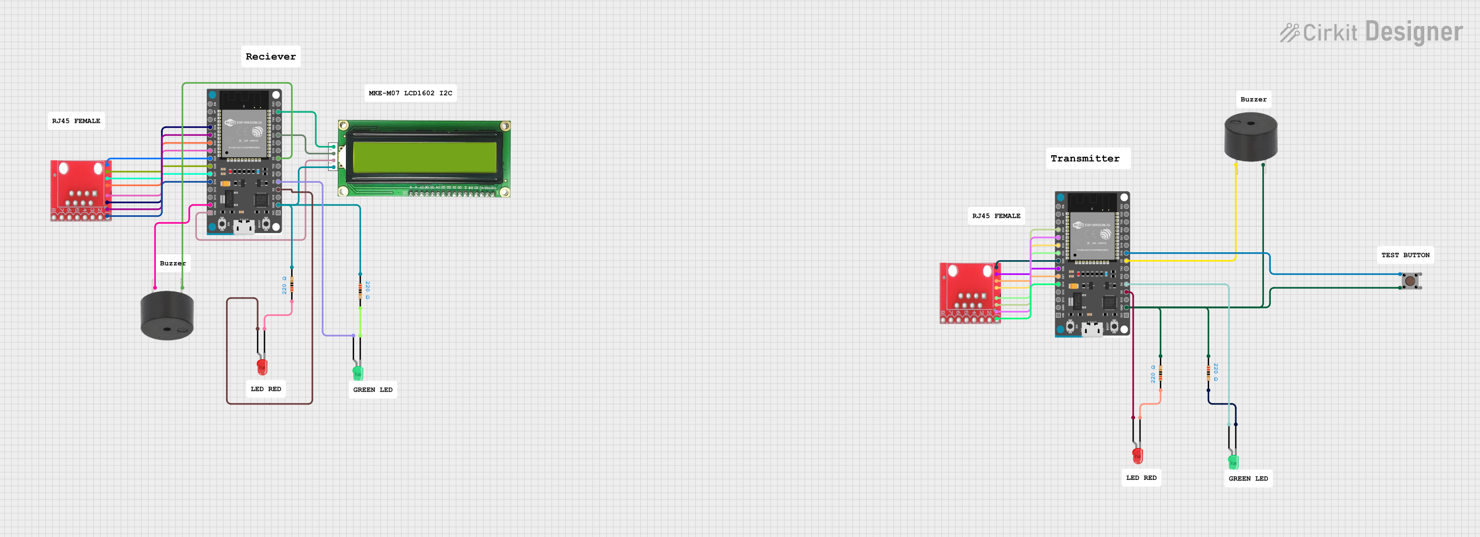
This circuit is a cable tester using two ESP32 microcontrollers to check the continuity and measure the length of RJ45 cables. It includes LEDs, a buzzer, and an LCD for visual and auditory feedback, and a pushbutton to initiate the test. The microcontrollers control the LEDs, buzzer, and LCD, and read the state of the RJ45 pins to determine connectivity and cable length.
Parallel Resistor Circuit Project
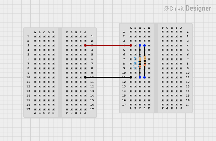
The circuit consists of two resistors, each with a resistance of 200 Ohms, connected in parallel. This configuration is used to combine the resistance values to effectively create a single resistor with a lower equivalent resistance, which would be 100 Ohms in this case.
Arduino UNO Quiz Game with 16x2 I2C LCD and Pushbuttons
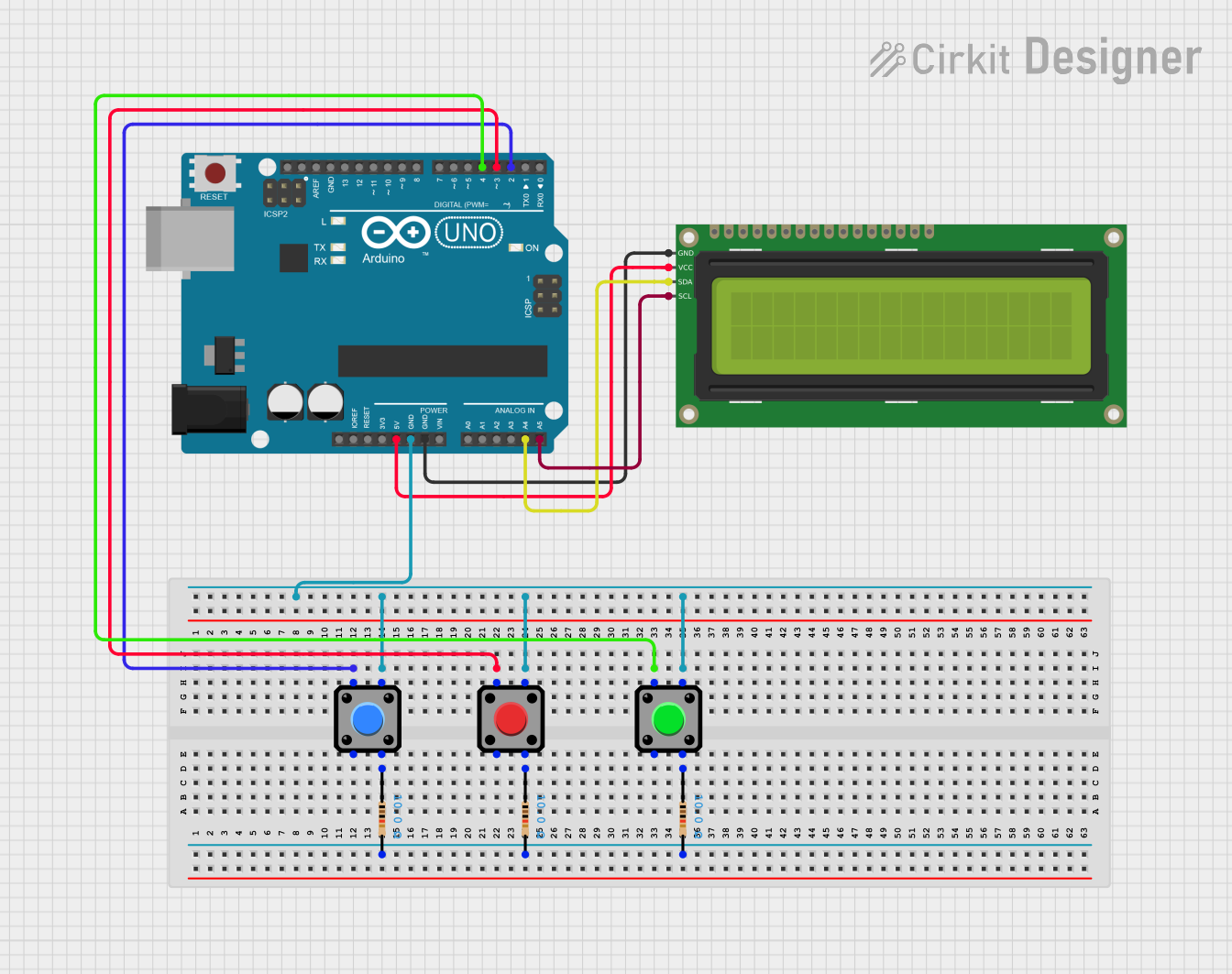
This circuit is a quiz game system using an Arduino UNO, a 16x2 I2C LCD, and three pushbuttons. The Arduino controls the LCD to display questions and receives user input through the buttons to check answers and track the score.
Explore Projects Built with Test 2
Arduino Mega 2560-Based Soil Nutrient Testing System with Bluetooth and LCD Display
This circuit is an automated chemical testing system controlled by an Arduino Mega 2560. It uses various sensors, including a turbidity sensor and a color sensor, to measure water quality parameters, and it communicates results via an LCD display and Bluetooth module. The system also controls multiple relays to dispense chemicals for different tests.
ESP32-Based RJ45 Cable Tester with LED Indicators and Buzzer
This circuit is a cable tester using two ESP32 microcontrollers to check the continuity and measure the length of RJ45 cables. It includes LEDs, a buzzer, and an LCD for visual and auditory feedback, and a pushbutton to initiate the test. The microcontrollers control the LEDs, buzzer, and LCD, and read the state of the RJ45 pins to determine connectivity and cable length.
Parallel Resistor Circuit Project
The circuit consists of two resistors, each with a resistance of 200 Ohms, connected in parallel. This configuration is used to combine the resistance values to effectively create a single resistor with a lower equivalent resistance, which would be 100 Ohms in this case.
Arduino UNO Quiz Game with 16x2 I2C LCD and Pushbuttons
This circuit is a quiz game system using an Arduino UNO, a 16x2 I2C LCD, and three pushbuttons. The Arduino controls the LCD to display questions and receives user input through the buttons to check answers and track the score.
Technical Specifications
Key Technical Details:
- Voltage Rating: N/A (placeholder component)
- Current Rating: N/A (placeholder component)
- Power Rating: N/A (placeholder component)
- Physical Dimensions: Variable, depending on simulation or educational setup
- Material: Virtual or generic placeholder material
Pin Configuration and Descriptions:
| Pin Number | Pin Name | Description |
|---|---|---|
| 1 | Input | Placeholder input terminal |
| 2 | Output | Placeholder output terminal |
Usage Instructions
How to Use the Component:
- Place the Test 2 component in your circuit design or simulation software.
- Connect the input and output pins to the desired circuit nodes.
- Use the component to verify the flow of signals or to test the layout of your circuit.
Important Considerations:
- Since Test 2 is a placeholder, it does not exhibit real-world electrical behavior. Replace it with an actual component for final testing.
- Ensure that the connections to the input and output pins are correct to avoid simulation errors.
- In educational setups, use Test 2 to demonstrate basic circuit principles without introducing unnecessary complexity.
Arduino UNO Example: While Test 2 is not a real-world component, it can be used in simulations involving Arduino UNO. Below is an example of how to simulate a basic circuit with a placeholder component:
// Example Arduino code for testing a placeholder component
// This code toggles a digital pin to simulate interaction with Test 2

const int testPin = 7; // Define the pin connected to Test 2

void setup() {
  pinMode(testPin, OUTPUT); // Set the pin as an output
}

void loop() {
  digitalWrite(testPin, HIGH); // Simulate sending a signal to Test 2
  delay(1000); // Wait for 1 second
  digitalWrite(testPin, LOW);  // Simulate stopping the signal
  delay(1000); // Wait for 1 second
}
Troubleshooting and FAQs
Common Issues:
- Simulation Errors: If the circuit simulation fails, ensure that the Test 2 component is properly connected to other components.
- Unexpected Behavior: Remember that Test 2 does not emulate real-world electrical properties. Replace it with a real component for accurate results.
Solutions and Tips:
- Double-check all connections in your circuit design.
- Use Test 2 only for testing and replace it with a real component for final implementation.
- If using simulation software, ensure that the software supports placeholder components like Test 2.
FAQs:
- Q: Can I use Test 2 in a real-world circuit?
A: No, Test 2 is a placeholder component and is not intended for real-world use. - Q: What is the purpose of Test 2?
A: It is used for testing, simulation, and educational purposes to verify circuit functionality.
- Q: Can I use Test 2 in a real-world circuit?