How to Use ESP32 DEV KIT V1: Examples, Pinouts, and Specs
Introduction
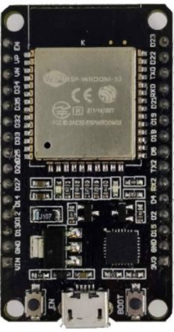
The ESP32 DEV KIT V1 is a versatile development board built around the powerful ESP32 chip. It features integrated Wi-Fi and Bluetooth capabilities, making it an excellent choice for Internet of Things (IoT) applications, wireless communication projects, and rapid prototyping. With its dual-core processor, low power consumption, and extensive GPIO pins, the ESP32 DEV KIT V1 is suitable for a wide range of applications, including smart home devices, wearable electronics, and industrial automation.
Explore Projects Built with ESP32 DEV KIT V1


Explore Projects Built with ESP32 DEV KIT V1
Technical Specifications
The ESP32 DEV KIT V1 is designed to provide robust performance and flexibility. Below are its key technical specifications:
- Microcontroller: ESP32-D0WDQ6 chip
- Processor: Dual-core 32-bit Xtensa LX6 CPU
- Clock Speed: Up to 240 MHz
- Flash Memory: 4 MB (varies by model)
- SRAM: 520 KB
- Connectivity: Wi-Fi 802.11 b/g/n, Bluetooth v4.2 (Classic and BLE)
- Operating Voltage: 3.3V
- Input Voltage (via USB): 5V
- GPIO Pins: 30 (varies slightly by board version)
- ADC Channels: 18 (12-bit resolution)
- DAC Channels: 2 (8-bit resolution)
- PWM Outputs: 16
- Communication Protocols: UART, SPI, I2C, I2S, CAN
- Power Consumption: Ultra-low power modes available
- Dimensions: Approximately 54mm x 27mm
Pin Configuration and Descriptions
The ESP32 DEV KIT V1 features a 30-pin layout. Below is the pin configuration and description:
| Pin | Name | Description |
|---|---|---|
| 1 | EN | Reset pin. Pulling this pin low resets the board. |
| 2 | 3V3 | 3.3V output pin. Provides power to external components. |
| 3 | GND | Ground pin. Connect to the ground of your circuit. |
| 4 | VIN | Input voltage pin (5V). Used to power the board via an external source. |
| 5-19 | GPIO0-GPIO39 | General-purpose input/output pins. Configurable for various functions. |
| 20 | ADC1/ADC2 | Analog-to-digital converter pins. Used for reading analog signals. |
| 21 | DAC1/DAC2 | Digital-to-analog converter pins. Used for generating analog output signals. |
| 22 | TXD0/RXD0 | UART0 communication pins. Used for serial communication. |
| 23 | SCL/SDA | I2C communication pins. |
| 24 | MOSI/MISO/SCK | SPI communication pins. |
| 25 | BOOT | Boot mode selection pin. Used for flashing firmware. |
Note: Not all GPIO pins support all functions. Refer to the ESP32 datasheet for detailed pin capabilities.
Usage Instructions
How to Use the ESP32 DEV KIT V1 in a Circuit
Powering the Board:
- Connect the board to your computer via a micro-USB cable for power and programming.
- Alternatively, supply 5V to the VIN pin or 3.3V to the 3V3 pin for external power.
Programming the Board:
- Install the Arduino IDE and add the ESP32 board support package.
- Select "ESP32 DEV MODULE" from the Tools > Board menu.
- Connect the board to your computer and select the appropriate COM port.
- Write your code and upload it to the board.
Connecting Peripherals:
- Use the GPIO pins to connect sensors, actuators, or other peripherals.
- Ensure that the voltage levels of connected devices are compatible with the ESP32 (3.3V logic).
Wi-Fi and Bluetooth Setup:
- Use the built-in libraries (
WiFi.handBluetoothSerial.h) to configure wireless communication.
- Use the built-in libraries (
Example Code: Blinking an LED
Below is an example of how to blink an LED connected to GPIO2 using the Arduino IDE:
// Example: Blink an LED connected to GPIO2 on the ESP32 DEV KIT V1

// Define the GPIO pin where the LED is connected
#define LED_PIN 2

void setup() {
  // Set the LED pin as an output
  pinMode(LED_PIN, OUTPUT);
}

void loop() {
  // Turn the LED on
  digitalWrite(LED_PIN, HIGH);
  delay(1000); // Wait for 1 second

  // Turn the LED off
  digitalWrite(LED_PIN, LOW);
  delay(1000); // Wait for 1 second
}
Important Considerations and Best Practices
- Voltage Levels: The ESP32 operates at 3.3V logic. Avoid connecting 5V signals directly to its GPIO pins. Use a level shifter if necessary.
- Power Supply: Ensure a stable power supply to avoid unexpected resets or malfunctions.
- Boot Mode: If the board does not enter programming mode, press and hold the BOOT button while uploading code.
- Wi-Fi Interference: Avoid placing the board near sources of electromagnetic interference to maintain reliable Wi-Fi performance.
Troubleshooting and FAQs
Common Issues and Solutions
Problem: The board is not detected by the computer.
Solution:- Ensure the USB cable is functional and supports data transfer.
- Install the correct USB-to-serial driver (e.g., CP2102 or CH340, depending on your board).
Problem: Code upload fails with a timeout error.
Solution:- Press and hold the BOOT button while uploading the code.
- Check that the correct COM port and board type are selected in the Arduino IDE.
Problem: Wi-Fi connection is unstable.
Solution:- Ensure the board is within range of the Wi-Fi router.
- Check for interference from other devices operating on the same frequency.
Problem: GPIO pins are not functioning as expected.
Solution:- Verify that the pins are not being used for other functions (e.g., ADC, UART).
- Check the ESP32 datasheet for pin-specific limitations.
FAQs
Q: Can I power the ESP32 DEV KIT V1 with a battery?
A: Yes, you can use a 3.7V LiPo battery connected to the 3V3 pin or a 5V source connected to the VIN pin.Q: How do I reset the board?
A: Press the EN (reset) button on the board to restart it.Q: Can I use the ESP32 DEV KIT V1 with MicroPython?
A: Yes, the ESP32 supports MicroPython. Flash the MicroPython firmware to the board and use a compatible IDE like Thonny.Q: What is the maximum number of devices that can connect to the ESP32 via Bluetooth?
A: The ESP32 can connect to up to 7 devices in Bluetooth Classic mode. For BLE, the number depends on the configuration.
By following this documentation, you can effectively use the ESP32 DEV KIT V1 for your projects and troubleshoot common issues with ease.