Cirkit Designer Logo
Cirkit Designer
Your all-in-one circuit design IDE
Home / 
Component Documentation

How to Use TB6612 (motor driver/PWM controller): Examples, Pinouts, and Specs

Image of TB6612 (motor driver/PWM controller)
Cirkit Designer LogoDesign with TB6612 (motor driver/PWM controller) in Cirkit Designer

Introduction

The TB6612 is a versatile and efficient motor driver and PWM (Pulse Width Modulation) controller designed to drive DC motors in various applications, including robotics, automation systems, and hobbyist projects. It offers the ability to control both the speed and direction of one or two DC motors and is known for its low power consumption and high efficiency.

Explore Projects Built with TB6612 (motor driver/PWM controller)

Use Cirkit Designer to design, explore, and prototype these projects online. Some projects support real-time simulation. Click "Open Project" to start designing instantly!
CNC Machine Control System with Dual tb6600 Stepper Drivers and MAch3 USB Interface
Image of Jayshree CNC: A project utilizing TB6612 (motor driver/PWM controller) in a practical application
This circuit appears to be a control system for a CNC machine or similar automated equipment. It includes two tb6600 Micro Stepping Motor Drivers for controlling stepper motors, a DC power source with a step-down buck converter to provide the necessary voltage levels, and a 4-channel relay module for switching higher power loads. The MAch3 CNC USB interface suggests the system is designed to interface with computer numerical control software, and the RMCS_3001 BLDC Driver indicates the presence of a brushless DC motor control. The Tiva C launchpad microcontroller and various connectors imply that the system is modular and may be programmable for specific automation tasks.
Cirkit Designer LogoOpen Project in Cirkit Designer
Stepper Motor Control System with TB6600 Driver and DKC-1A Controller
Image of Copy of Copy of PLC-Based Step Motor Speed and Direction Control System: A project utilizing TB6612 (motor driver/PWM controller) in a practical application
This circuit controls a bipolar stepper motor using a tb6600 micro stepping motor driver and a DKC-1A stepper motor controller. The system is powered by a 24VDC power supply and includes a relay module for additional control functionalities.
Cirkit Designer LogoOpen Project in Cirkit Designer
Arduino-Controlled Dual Motor Driver with IR Sensing
Image of Line follower 14 IR Sensor channel: A project utilizing TB6612 (motor driver/PWM controller) in a practical application
This circuit controls two DC motors using a TB6612FNG motor driver, which is interfaced with an Arduino Mega 2560 microcontroller. The Arduino provides PWM signals to control the speed and direction of the motors. Multiple IR sensors are connected to the Arduino's analog inputs, likely for sensing the environment or for line-following capabilities in a robot.
Cirkit Designer LogoOpen Project in Cirkit Designer
Stepper Motor Control System with TB6600 Driver and Relay Integration
Image of Copy of Copy of Copy of PLC-Based Step Motor Speed and Direction Control System: A project utilizing TB6612 (motor driver/PWM controller) in a practical application
This circuit controls a bipolar stepper motor using a tb6600 micro stepping motor driver and a DKC-1A stepper motor controller. It includes a 24VDC power supply, a 4-channel relay module, and panel mount banana sockets for power connections. The motor driver and controller are interconnected to manage the motor's direction and pulse signals.
Cirkit Designer LogoOpen Project in Cirkit Designer

Explore Projects Built with TB6612 (motor driver/PWM controller)

Use Cirkit Designer to design, explore, and prototype these projects online. Some projects support real-time simulation. Click "Open Project" to start designing instantly!
Image of Jayshree CNC: A project utilizing TB6612 (motor driver/PWM controller) in a practical application
CNC Machine Control System with Dual tb6600 Stepper Drivers and MAch3 USB Interface
This circuit appears to be a control system for a CNC machine or similar automated equipment. It includes two tb6600 Micro Stepping Motor Drivers for controlling stepper motors, a DC power source with a step-down buck converter to provide the necessary voltage levels, and a 4-channel relay module for switching higher power loads. The MAch3 CNC USB interface suggests the system is designed to interface with computer numerical control software, and the RMCS_3001 BLDC Driver indicates the presence of a brushless DC motor control. The Tiva C launchpad microcontroller and various connectors imply that the system is modular and may be programmable for specific automation tasks.
Cirkit Designer LogoOpen Project in Cirkit Designer
Image of Copy of Copy of PLC-Based Step Motor Speed and Direction Control System: A project utilizing TB6612 (motor driver/PWM controller) in a practical application
Stepper Motor Control System with TB6600 Driver and DKC-1A Controller
This circuit controls a bipolar stepper motor using a tb6600 micro stepping motor driver and a DKC-1A stepper motor controller. The system is powered by a 24VDC power supply and includes a relay module for additional control functionalities.
Cirkit Designer LogoOpen Project in Cirkit Designer
Image of Line follower 14 IR Sensor channel: A project utilizing TB6612 (motor driver/PWM controller) in a practical application
Arduino-Controlled Dual Motor Driver with IR Sensing
This circuit controls two DC motors using a TB6612FNG motor driver, which is interfaced with an Arduino Mega 2560 microcontroller. The Arduino provides PWM signals to control the speed and direction of the motors. Multiple IR sensors are connected to the Arduino's analog inputs, likely for sensing the environment or for line-following capabilities in a robot.
Cirkit Designer LogoOpen Project in Cirkit Designer
Image of Copy of Copy of Copy of PLC-Based Step Motor Speed and Direction Control System: A project utilizing TB6612 (motor driver/PWM controller) in a practical application
Stepper Motor Control System with TB6600 Driver and Relay Integration
This circuit controls a bipolar stepper motor using a tb6600 micro stepping motor driver and a DKC-1A stepper motor controller. It includes a 24VDC power supply, a 4-channel relay module, and panel mount banana sockets for power connections. The motor driver and controller are interconnected to manage the motor's direction and pulse signals.
Cirkit Designer LogoOpen Project in Cirkit Designer

Common Applications and Use Cases

  • Robotics: Driving wheels or actuator motors.
  • Automation systems: Conveyor belts, positioning motors.
  • Hobby projects: Remote-controlled vehicles, DIY electronic gadgets.

Technical Specifications

Key Technical Details

  • Supply Voltage (VM): 2.5V to 13.5V
  • Logic Voltage (VCC): 2.7V to 5.5V
  • Output Current (continuous): 1.2A per channel
  • Output Current (peak): 3.2A per channel
  • Standby Control to Save Power

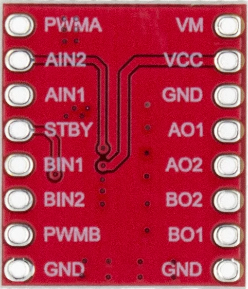
Pin Configuration and Descriptions

Pin Number Pin Name Description
1 VM Motor voltage supply (2.5V to 13.5V)
2 VCC Logic voltage supply (2.7V to 5.5V)
3 GND Ground
4 STBY Standby (Low: Standby mode, High: Normal operation)
5 AIN1 Input A channel 1
6 AIN2 Input A channel 2
7 PWMA PWM input for A channel
8 BIN1 Input B channel 1
9 BIN2 Input B channel 2
10 PWMB PWM input for B channel
11 AOUT1 Output A channel 1
12 AOUT2 Output A channel 2
13 BOUT1 Output B channel 1
14 BOUT2 Output B channel 2

Usage Instructions

How to Use the TB6612 in a Circuit

  1. Power Connections:

    • Connect the motor supply voltage (VM) to pin 1.
    • Connect the logic supply voltage (VCC) to pin 2.
    • Connect the ground (GND) to pin 3.
  2. Motor Connections:

    • Connect the terminals of motor A to AOUT1 and AOUT2.
    • Connect the terminals of motor B to BOUT1 and BOUT2, if using a second motor.
  3. Control Connections:

    • Connect the microcontroller or control device to AIN1, AIN2, PWMA for motor A.
    • Connect the microcontroller or control device to BIN1, BIN2, PWMB for motor B.
  4. Standby Mode:

    • Connect STBY to a digital pin on the microcontroller to enable or disable the motor driver.

Important Considerations and Best Practices

  • Ensure that the supply voltage does not exceed the maximum ratings.
  • Use a common ground for both the logic and motor power supplies.
  • Avoid running motors at the peak current for extended periods to prevent overheating.
  • Implement proper decoupling using capacitors close to the motor driver to minimize noise.

Example Code for Arduino UNO

#include <Arduino.h>

// Define TB6612 control pins connected to the Arduino
const int PWMA = 3; // Speed control for motor A
const int AIN1 = 4; // Direction control for motor A
const int AIN2 = 5; // Direction control for motor A
const int STBY = 6; // Standby

void setup() {
  // Set control pins as outputs
  pinMode(PWMA, OUTPUT);
  pinMode(AIN1, OUTPUT);
  pinMode(AIN2, OUTPUT);
  pinMode(STBY, OUTPUT);

  // Disable standby mode
  digitalWrite(STBY, HIGH);
}

void loop() {
  // Set motor A direction to clockwise
  digitalWrite(AIN1, HIGH);
  digitalWrite(AIN2, LOW);

  // Set motor A speed to 50%
  analogWrite(PWMA, 128);

  delay(2000); // Run for 2 seconds

  // Set motor A direction to counter-clockwise
  digitalWrite(AIN1, LOW);
  digitalWrite(AIN2, HIGH);

  delay(2000); // Run for 2 seconds

  // Stop motor A
  digitalWrite(AIN1, LOW);
  digitalWrite(AIN2, LOW);

  delay(2000); // Stop for 2 seconds
}

Troubleshooting and FAQs

Common Issues Users Might Face

  • Motor not running: Check power supply connections, ensure STBY is set to HIGH.
  • Motor running only in one direction: Verify the logic inputs AIN1 and AIN2.
  • Motor stuttering or weak: Ensure the power supply can deliver sufficient current.

Solutions and Tips for Troubleshooting

  • Double-check wiring against the pin configuration table.
  • Use a multimeter to verify the voltage levels at the power supply and logic inputs.
  • Ensure that the PWM frequency is within the acceptable range for the TB6612.

FAQs

Q: Can the TB6612 drive stepper motors? A: No, the TB6612 is designed for DC motors. Stepper motors require a different type of driver.

Q: What is the maximum frequency for PWM input? A: The TB6612 can handle PWM frequencies up to 100kHz.

Q: How do I put the TB6612 in standby mode? A: Set the STBY pin to LOW to put the TB6612 in standby mode and reduce power consumption.

Q: Can I use the TB6612 to drive a single motor at 2.4A? A: No, the continuous current per channel is 1.2A. To drive a motor with higher current, consider using a motor driver with a higher current rating or paralleling the outputs with proper current sharing.

This documentation provides a comprehensive guide to using the TB6612 motor driver/PWM controller. For further information, consult the manufacturer's datasheet and application notes.