How to Use JST Male: Examples, Pinouts, and Specs
Introduction
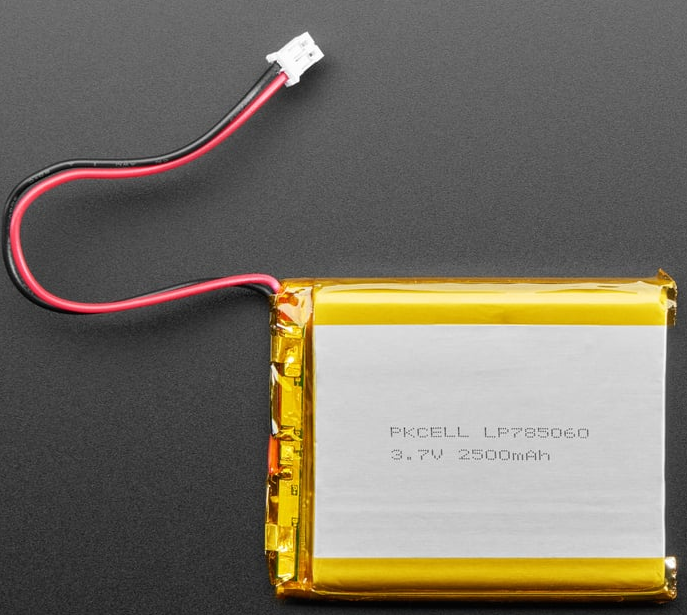
The JST Male connector, manufactured by Adafruit, is a widely used electrical connector designed for joining wires in a circuit. It features a male pin design that mates with a corresponding female connector, ensuring a secure and reliable connection for both power and signal transmission. These connectors are compact, lightweight, and easy to use, making them ideal for a variety of applications.
Explore Projects Built with JST Male


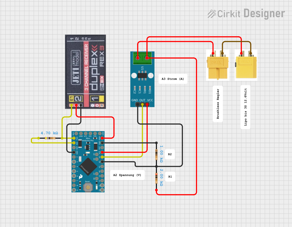
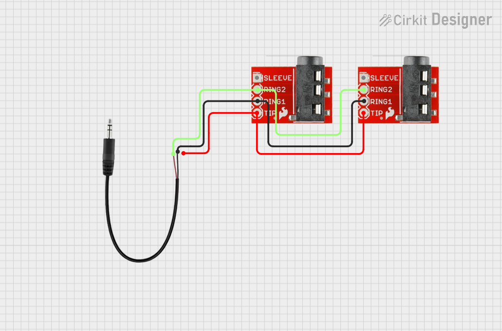
Explore Projects Built with JST Male
Common Applications and Use Cases
- Power connections in small electronic devices
- Signal transmission in robotics and drones
- Battery connections for LiPo (Lithium Polymer) batteries
- Prototyping and DIY electronics projects
- Embedded systems and IoT devices
Technical Specifications
The JST Male connector is designed to meet the needs of low-power and signal applications. Below are the key technical details:
| Specification | Details |
|---|---|
| Manufacturer | Adafruit |
| Connector Type | JST Male |
| Pin Count | 2 pins (standard) |
| Current Rating | Up to 3A |
| Voltage Rating | Up to 250V |
| Wire Gauge Compatibility | 22-28 AWG |
| Material | Plastic housing, metal pins |
| Operating Temperature | -25°C to 85°C |
| Mating Cycles | 50 cycles (typical) |
Pin Configuration and Descriptions
The JST Male connector typically has two pins, which are used for power and ground connections. Below is the pin configuration:
| Pin Number | Name | Description |
|---|---|---|
| 1 | VCC (+) | Positive voltage or power input |
| 2 | GND (-) | Ground or negative voltage |
Usage Instructions
How to Use the JST Male Connector in a Circuit
- Prepare the Wires: Strip the insulation from the ends of the wires you want to connect, ensuring the exposed length matches the connector's crimp terminals.
- Crimp the Wires: Use a crimping tool to attach the wires to the metal pins of the JST Male connector. Ensure a secure and firm connection.
- Insert the Pins: Push the crimped pins into the plastic housing of the JST Male connector until they click into place.
- Connect to Female Connector: Align the JST Male connector with the corresponding JST Female connector and gently push them together until they lock.
Important Considerations and Best Practices
- Wire Gauge: Ensure the wires used are within the compatible range (22-28 AWG) for optimal performance.
- Polarity: Double-check the polarity of the connections (VCC and GND) to avoid damaging your circuit.
- Secure Connections: Use heat shrink tubing or electrical tape to insulate exposed wires and prevent short circuits.
- Avoid Overcurrent: Do not exceed the current rating (3A) to prevent overheating or damage to the connector.
Example: Connecting to an Arduino UNO
The JST Male connector can be used to power an Arduino UNO via a LiPo battery. Below is an example of how to connect and use it:
- Connect the VCC pin of the JST Male connector to the VIN pin of the Arduino UNO.
- Connect the GND pin of the JST Male connector to the GND pin of the Arduino UNO.
Sample Arduino Code
// Example code to read a sensor powered by a LiPo battery connected via a JST Male
// connector. Ensure the battery is properly connected to the Arduino's VIN and GND.

const int sensorPin = A0; // Analog pin connected to the sensor
int sensorValue = 0;      // Variable to store the sensor reading

void setup() {
  Serial.begin(9600); // Initialize serial communication at 9600 baud
  pinMode(sensorPin, INPUT); // Set the sensor pin as an input
}

void loop() {
  sensorValue = analogRead(sensorPin); // Read the sensor value
  Serial.print("Sensor Value: ");
  Serial.println(sensorValue); // Print the sensor value to the Serial Monitor
  delay(1000); // Wait for 1 second before the next reading
}
Troubleshooting and FAQs
Common Issues and Solutions
Loose Connections:
- Issue: The connector feels loose or disconnects easily.
- Solution: Ensure the crimped pins are securely inserted into the housing. Replace damaged pins or housing if necessary.
Polarity Reversal:
- Issue: The circuit does not work or components are damaged.
- Solution: Double-check the polarity of the connections (VCC and GND) before powering the circuit.
Overheating:
- Issue: The connector becomes hot during operation.
- Solution: Verify that the current does not exceed the 3A rating. Use thicker wires if necessary.
Difficulty Crimping Wires:
- Issue: The wires do not stay attached to the pins.
- Solution: Use a proper crimping tool designed for JST connectors and ensure the wire gauge is compatible.
FAQs
Q1: Can I use the JST Male connector for high-power applications?
A1: No, the JST Male connector is designed for low-power applications with a maximum current rating of 3A. For high-power applications, consider using connectors with higher current ratings.
Q2: How do I remove the pins from the housing?
A2: Use a small flathead screwdriver or a pin removal tool to gently release the locking tabs inside the housing and pull the pins out.
Q3: Are JST connectors waterproof?
A3: Standard JST connectors are not waterproof. For outdoor or moisture-prone environments, use waterproof connectors or enclosures.
Q4: Can I solder wires directly to the pins?
A4: While crimping is recommended, you can solder wires to the pins if you do not have a crimping tool. Ensure the solder joints are clean and insulated.