How to Use ADXL375 High G Accelerometer: Examples, Pinouts, and Specs
ADXL375 High G Accelerometer Documentation
1. Introduction
The ADXL375 is a high-performance, 3-axis digital accelerometer designed to measure acceleration forces up to ±200g. It is ideal for applications requiring high sensitivity, precision, and the ability to withstand extreme acceleration forces. The device communicates via an SPI or I²C digital interface, making it easy to integrate into a wide range of systems.
Common Applications
- Impact and shock detection
- Sports equipment performance monitoring
- Industrial vibration analysis
- Automotive crash testing
- Aerospace and defense systems
- Wearable devices for motion tracking
The ADXL375 is a robust and versatile sensor, offering high-resolution acceleration data in a compact package.
2. Technical Specifications
The following table outlines the key technical details of the ADXL375:
| Parameter | Value |
|---|---|
| Measurement Range | ±200g |
| Sensitivity | 0.049 g/LSB |
| Supply Voltage (VDD) | 2.0V to 3.6V |
| Interface | SPI (4-wire) / I²C |
| Output Data Rate (ODR) | 0.1 Hz to 3200 Hz |
| Operating Temperature Range | -40°C to +85°C |
| Power Consumption | 140 µA (typical at 2.5V, 100 Hz) |
| Dimensions | 3 mm × 5 mm × 1 mm (LGA package) |
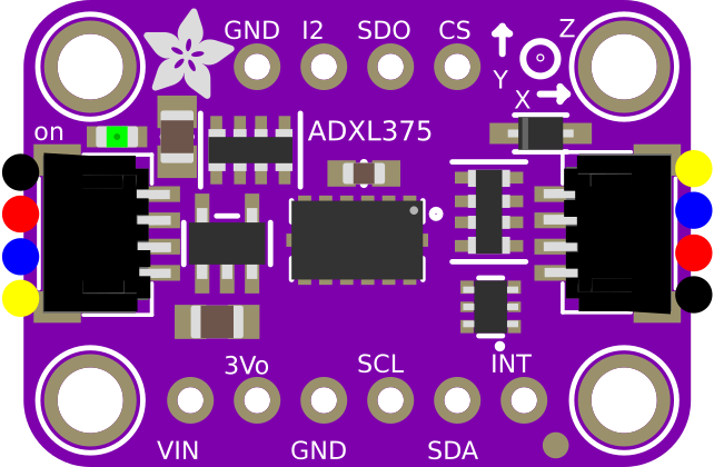
Pin Configuration and Descriptions
The ADXL375 is available in a 14-pin LGA package. The pinout and descriptions are as follows:
| Pin | Name | Description |
|---|---|---|
| 1 | VDD | Power supply input (2.0V to 3.6V). |
| 2 | GND | Ground reference. |
| 3 | CS | Chip Select (active low). Used to select the device in SPI mode. |
| 4 | SCL/SCLK | Serial Clock. Used for I²C or SPI communication. |
| 5 | SDA/SDI | Serial Data Input (I²C) or Data Input (SPI). |
| 6 | SDO/ALT | Serial Data Output (SPI) or Alternate Address Select (I²C). |
| 7-14 | NC | No connection. These pins should be left unconnected or tied to ground. |
3. Usage Instructions
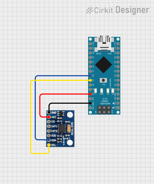
Connecting the ADXL375 to an Arduino UNO
The ADXL375 can be interfaced with an Arduino UNO using either SPI or I²C communication. Below is an example of how to connect the ADXL375 to the Arduino UNO using the SPI interface:
| ADXL375 Pin | Arduino UNO Pin |
|---|---|
| VDD | 3.3V |
| GND | GND |
| CS | Pin 10 |
| SCL/SCLK | Pin 13 |
| SDA/SDI | Pin 11 |
| SDO/ALT | Pin 12 |
Example Code: Reading Acceleration Data via SPI
The following Arduino sketch demonstrates how to read acceleration data from the ADXL375 using SPI:
#include <SPI.h>

// Define ADXL375 SPI pins
const int CS_PIN = 10; // Chip Select pin

// ADXL375 register addresses
#define POWER_CTL 0x2D
#define DATA_FORMAT 0x31
#define DATAX0 0x32

void setup() {
  // Initialize serial communication
  Serial.begin(9600);

  // Set up SPI
  SPI.begin();
  pinMode(CS_PIN, OUTPUT);
  digitalWrite(CS_PIN, HIGH); // Deselect the sensor

  // Initialize ADXL375
  initializeADXL375();
}

void loop() {
  // Read acceleration data
  int16_t x = readAxis(DATAX0);
  int16_t y = readAxis(DATAX0 + 2);
  int16_t z = readAxis(DATAX0 + 4);

  // Convert raw data to g-force
  float x_g = x * 0.049; // Sensitivity: 0.049 g/LSB
  float y_g = y * 0.049;
  float z_g = z * 0.049;

  // Print acceleration data
  Serial.print("X: ");
  Serial.print(x_g);
  Serial.print(" g, Y: ");
  Serial.print(y_g);
  Serial.print(" g, Z: ");
  Serial.print(z_g);
  Serial.println(" g");

  delay(500); // Wait for 500ms
}

void initializeADXL375() {
  // Set the device to measurement mode
  writeRegister(POWER_CTL, 0x08);

  // Set data format to full resolution, ±200g
  writeRegister(DATA_FORMAT, 0x0B);
}

void writeRegister(byte reg, byte value) {
  digitalWrite(CS_PIN, LOW); // Select the sensor
  SPI.transfer(reg);
  SPI.transfer(value);
  digitalWrite(CS_PIN, HIGH); // Deselect the sensor
}

int16_t readAxis(byte reg) {
  digitalWrite(CS_PIN, LOW); // Select the sensor
  SPI.transfer(reg | 0x80);  // Read command (MSB = 1)
  byte lowByte = SPI.transfer(0x00);
  byte highByte = SPI.transfer(0x00);
  digitalWrite(CS_PIN, HIGH); // Deselect the sensor

  // Combine high and low bytes
  return (int16_t)((highByte << 8) | lowByte);
}
Important Considerations
- Power Supply: Ensure the ADXL375 is powered with a stable voltage between 2.0V and 3.6V. Using a voltage outside this range may damage the device.
- Communication Mode: Configure the device for SPI or I²C communication based on your application. Ensure proper pull-up resistors are used for I²C.
- Mounting: Securely mount the ADXL375 to minimize noise and vibration artifacts in the measurements.
- Data Rate: Select an appropriate output data rate (ODR) to balance power consumption and performance.
4. Troubleshooting and FAQs
Common Issues and Solutions
| Issue | Possible Cause | Solution |
|---|---|---|
| No data output | Incorrect wiring or communication settings | Verify connections and ensure SPI/I²C settings match the ADXL375 configuration. |
| Inconsistent or noisy readings | Excessive vibration or loose mounting | Securely mount the sensor and reduce external noise sources. |
| Device not responding to commands | Incorrect power supply voltage | Ensure the supply voltage is within the 2.0V to 3.6V range. |
| Incorrect acceleration values | Misconfigured data format or sensitivity | Verify the data format and sensitivity settings in the initialization code. |
Frequently Asked Questions
Can the ADXL375 measure static acceleration (e.g., gravity)?
- Yes, the ADXL375 can measure both static and dynamic acceleration, including gravity.
What is the maximum sampling rate of the ADXL375?
- The maximum output data rate (ODR) is 3200 Hz.
Can I use the ADXL375 with a 5V microcontroller?
- Yes, but you must use a logic level shifter to interface the 3.3V ADXL375 with a 5V microcontroller.
How do I switch between SPI and I²C modes?
- The communication mode is determined by the wiring of the SDO/ALT pin. Refer to the datasheet for details.
This documentation provides a comprehensive guide to using the ADXL375 High G Accelerometer. For further details, refer to the official datasheet or contact the manufacturer.
Explore Projects Built with ADXL375 High G Accelerometer

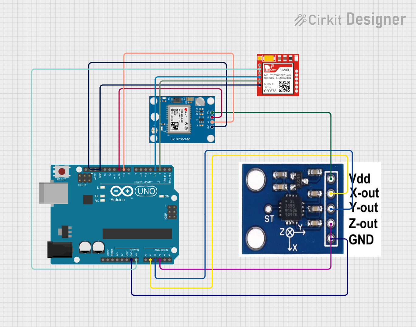
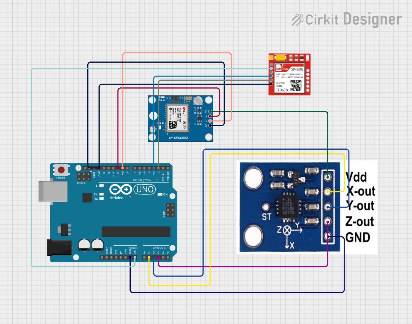
Explore Projects Built with ADXL375 High G Accelerometer