How to Use SparkFun-74HC4051-8-Channel-Mux-Breakout: Examples, Pinouts, and Specs
Introduction
The SparkFun 74HC4051 8-Channel Mux Breakout is a versatile multiplexer that significantly expands the number of analog inputs available on a microcontroller. This breakout board utilizes the 74HC4051 integrated circuit, which is an 8-channel analog multiplexer/demultiplexer. It is commonly used in applications where there is a need to route multiple signal lines through a single common channel, such as in data acquisition systems, signal switching, and sensor interfacing.
Explore Projects Built with SparkFun-74HC4051-8-Channel-Mux-Breakout


Explore Projects Built with SparkFun-74HC4051-8-Channel-Mux-Breakout
Technical Specifications
Key Technical Details
- Operating Voltage: 2V to 6V
- On-Resistance: 70 Ohms @ 4.5V
- On-Time: 250ns @ 4.5V
- Off-Leak Current: 100nA @ 4.5V
- Channel On Capacitance: 5pF (typical)
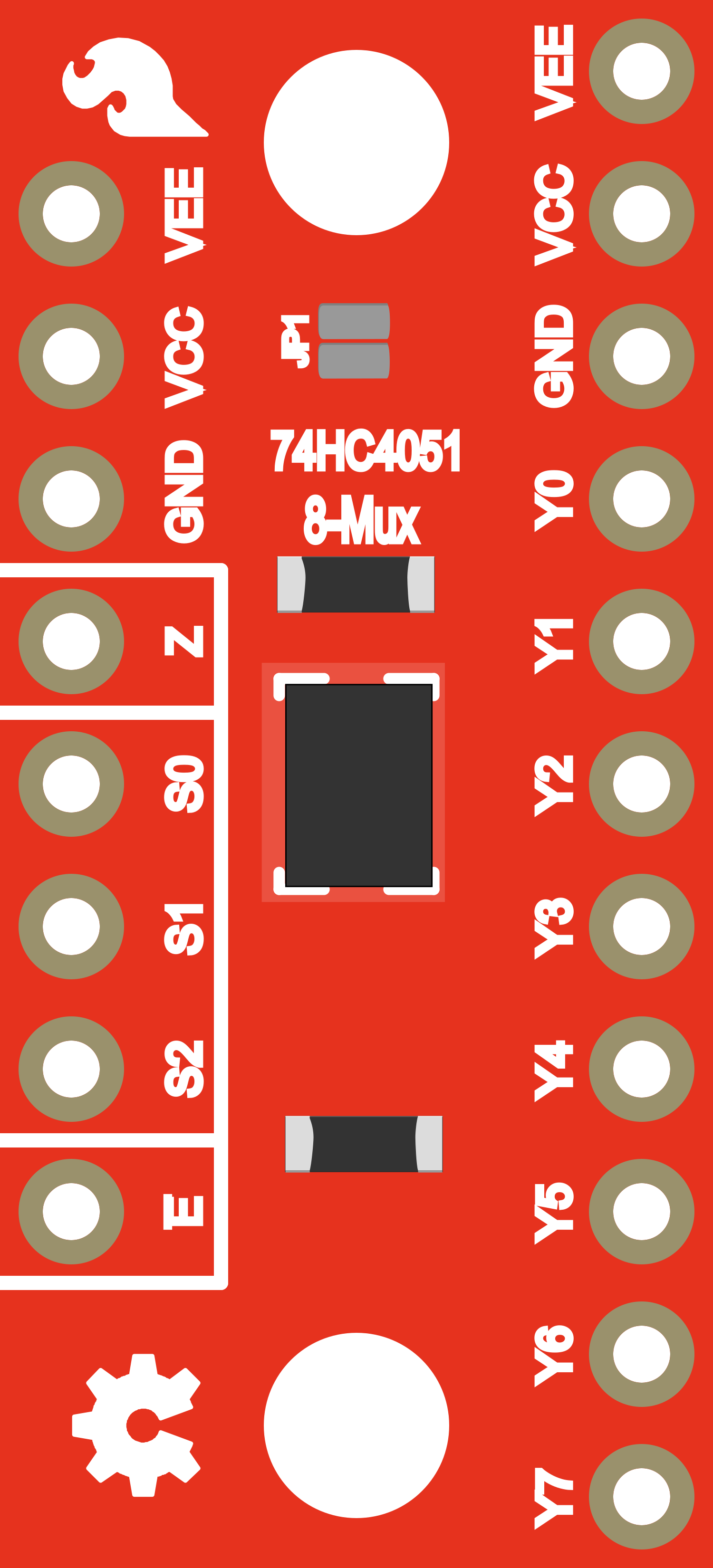
Pin Configuration and Descriptions
| Pin Number | Name | Description |
|---|---|---|
| 1 | S0 | Digital control input 0 |
| 2 | S1 | Digital control input 1 |
| 3 | S2 | Digital control input 2 |
| 4 | Z | Common output/input |
| 5 | E | Enable input (active low) |
| 6 | Vee | Ground reference for analog signals |
| 7 | Y7 | Analog input/output channel 7 |
| ... | ... | ... |
| 14 | Y0 | Analog input/output channel 0 |
| 15 | Vcc | Supply voltage |
| 16 | GND | Ground |
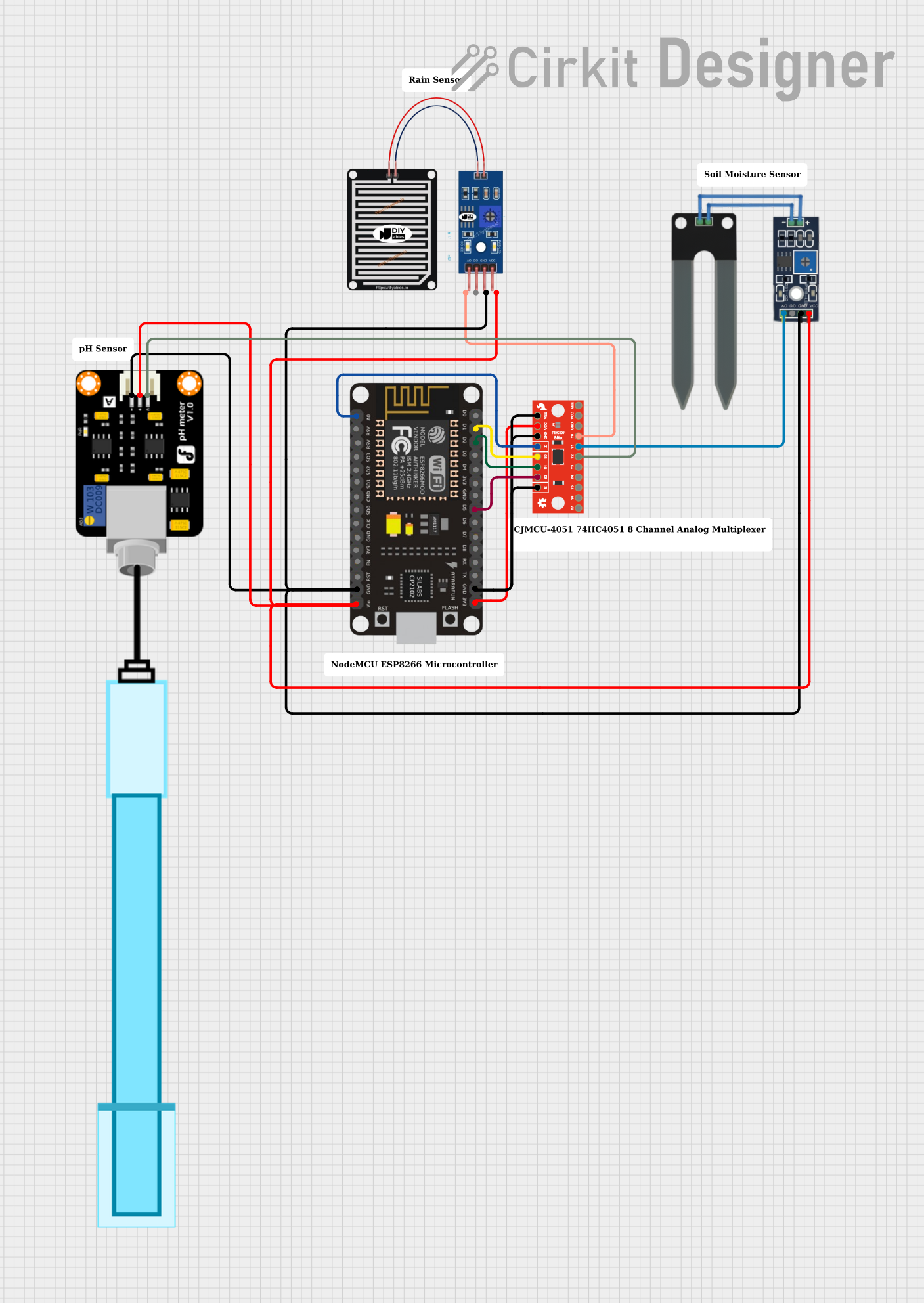
Usage Instructions
How to Use the Component in a Circuit
- Connect Vcc to your microcontroller's supply voltage (ensure it is within the operating voltage range).
- Connect GND to the ground of your microcontroller.
- Connect S0, S1, and S2 to digital outputs on your microcontroller to select the active channel.
- Connect Z to the analog input pin on your microcontroller.
- Connect the analog signals you wish to multiplex to Y0 through Y7.
- Connect E to ground to enable the device, or to a digital pin if you wish to control the enable function programmatically.
Important Considerations and Best Practices
- Ensure that the voltage levels on the analog signals do not exceed the Vcc of the 74HC4051.
- Keep the analog signal paths as short as possible to minimize noise and interference.
- Use pull-down or pull-up resistors on the control lines to ensure a known state when the microcontroller pins are floating.
- When not using the multiplexer, set the E pin high to disable it and prevent any unwanted signal routing.
Example Code for Arduino UNO
// Define the control pins for the 74HC4051
const int s0 = 2;
const int s1 = 3;
const int s2 = 4;
const int enablePin = 5; // Optional: Connect to GND if always enabled

void setup() {
  // Set up the control pins as outputs
  pinMode(s0, OUTPUT);
  pinMode(s1, OUTPUT);
  pinMode(s2, OUTPUT);
  pinMode(enablePin, OUTPUT);

  // Disable the multiplexer to start with
  digitalWrite(enablePin, HIGH);
}

void loop() {
  // Enable the multiplexer
  digitalWrite(enablePin, LOW);

  // Loop through all 8 channels
  for (int i = 0; i < 8; i++) {
    // Set the control pins to select the channel
    digitalWrite(s0, (i & 1) ? HIGH : LOW);
    digitalWrite(s1, (i & 2) ? HIGH : LOW);
    digitalWrite(s2, (i & 4) ? HIGH : LOW);

    // Read the selected channel (assuming it is connected to A0)
    int sensorValue = analogRead(A0);

    // Process the sensor value (e.g., print it)
    Serial.println(sensorValue);

    // Add a delay for stability
    delay(100);
  }

  // Disable the multiplexer after reading all channels
  digitalWrite(enablePin, HIGH);

  // Add a delay before the next read cycle
  delay(1000);
}
Troubleshooting and FAQs
Common Issues
- No Signal Detected: Ensure that the enable pin (E) is set to low to activate the multiplexer. Also, check that the control pins (S0, S1, S2) are correctly connected and programmed to select the desired channel.
- Inaccurate Readings: Verify that the analog signal levels are within the specified range for the Vcc of the 74HC4051. Also, check for any noise in the signal lines and consider using shielded cables if necessary.
- Intermittent Functionality: Check for loose connections and ensure that the power supply is stable and within the operating voltage range.
FAQs
Q: Can I use the 74HC4051 with a 3.3V microcontroller? A: Yes, the 74HC4051 can operate at voltages as low as 2V, making it compatible with 3.3V systems.
Q: How do I select which channel is active? A: The active channel is selected by setting the S0, S1, and S2 pins to the appropriate binary value corresponding to the desired channel number (0-7).
Q: Can the 74HC4051 be used with digital signals? A: Yes, while it is designed for analog signals, it can also be used to route digital signals.
Remember to always consult the datasheet for the most detailed and specific information regarding the operation and limitations of the 74HC4051.