Cirkit Designer Logo
Cirkit Designer
Your all-in-one circuit design IDE
Home / 
Component Documentation

How to Use MKE-M12 5VDC 5A Power Supply Module: Examples, Pinouts, and Specs

Image of MKE-M12 5VDC 5A Power Supply Module
Cirkit Designer LogoDesign with MKE-M12 5VDC 5A Power Supply Module in Cirkit Designer

Introduction

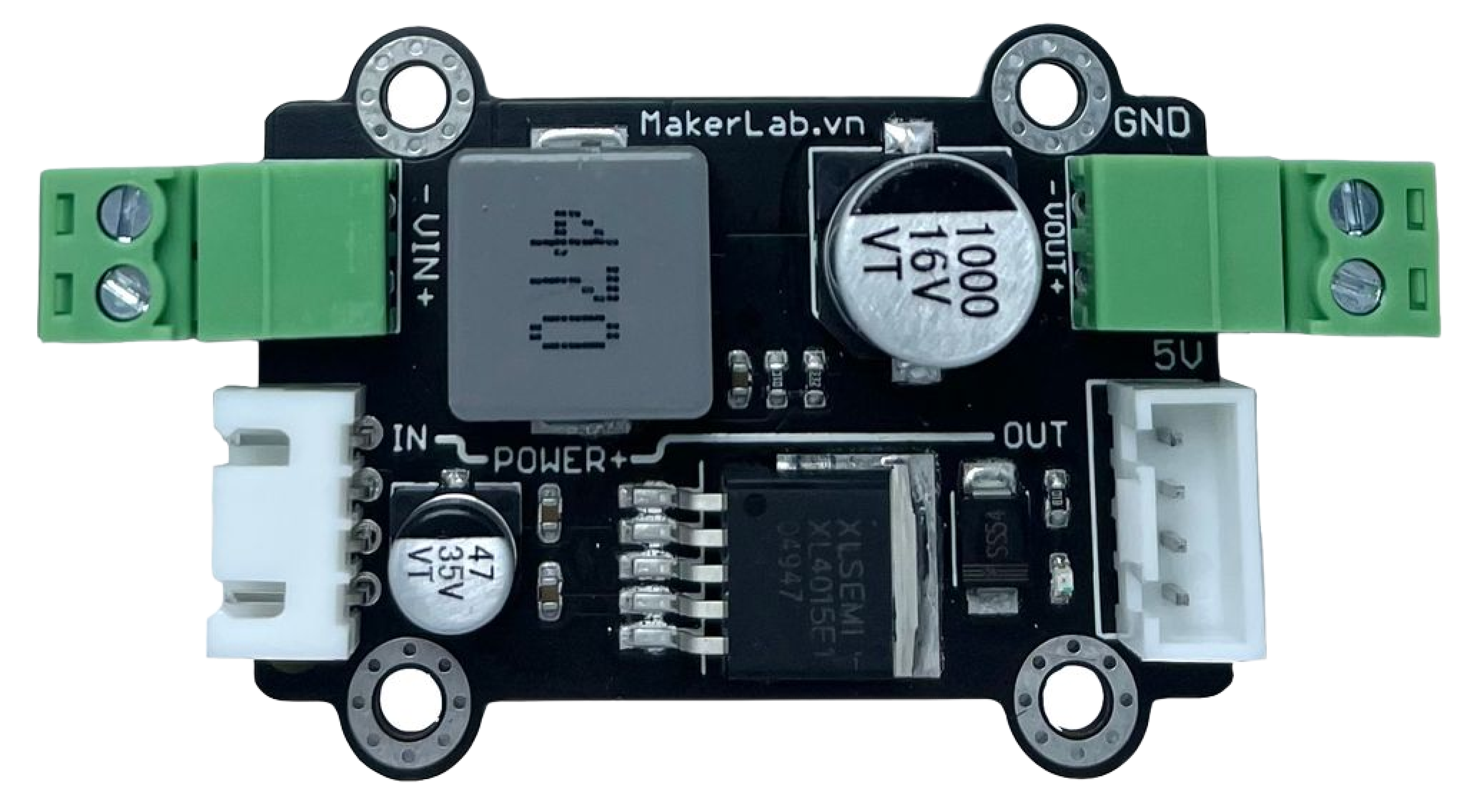
The MKE-M12 5VDC 5A Power Supply Module is a compact and efficient solution for providing a stable 5V DC power supply to electronic devices and circuits. With its capability to deliver up to 5A of current, it is ideal for powering a wide range of applications, including microcontrollers like Arduino, Raspberry Pi, sensors, and small motors.

Explore Projects Built with MKE-M12 5VDC 5A Power Supply Module

Use Cirkit Designer to design, explore, and prototype these projects online. Some projects support real-time simulation. Click "Open Project" to start designing instantly!
12V UPS System with Dual 18650 Li-ion Battery Backup and Voltage Regulation
Image of Power supply: A project utilizing MKE-M12 5VDC 5A Power Supply Module in a practical application
This circuit is designed to provide an uninterruptible power supply (UPS) system with a 12V DC output. It includes a 12V 5A power supply connected to an AC source through a toggle switch, which charges a pair of 18650 Li-ion batteries via a voltage regulator (XL4016). The UPS module ensures a continuous power supply to the load by switching between the power supply and the battery bank.
Cirkit Designer LogoOpen Project in Cirkit Designer
DC-DC Converter and Relay Module Power Distribution System
Image of relay: A project utilizing MKE-M12 5VDC 5A Power Supply Module in a practical application
This circuit consists of a DC-DC converter powering a 6-channel power module, which in turn supplies 5V to a 2-relay module. The power module distributes the converted voltage to the relay module, enabling it to control external devices.
Cirkit Designer LogoOpen Project in Cirkit Designer
Dual 5V Power Supply Distribution Circuit with Toggle Switch Control
Image of rfdriver: A project utilizing MKE-M12 5VDC 5A Power Supply Module in a practical application
This circuit consists of two 5V 5A power supplies connected to an AC wall plug point, providing DC output through a 12-way connector. The ground connections from both power supplies are interconnected and also connected to the ground pins of two toggle switches. The DC outputs from the power supplies are separately connected to different pins on the 12-way connector, with each power supply output being switchable via one of the toggle switches.
Cirkit Designer LogoOpen Project in Cirkit Designer
12V to 5V Power Supply with LED Indicator and Push Switch
Image of Power Supply LVCO: A project utilizing MKE-M12 5VDC 5A Power Supply Module in a practical application
This circuit is a 12V to 5V regulated power supply with an LED indicator. It uses a 5408 diode for reverse polarity protection, an LM340T5 7805 voltage regulator to step down the voltage to 5V, and a push switch to control the LED indicator. The circuit also includes capacitors for filtering and a resistor to limit the current through the LED.
Cirkit Designer LogoOpen Project in Cirkit Designer

Explore Projects Built with MKE-M12 5VDC 5A Power Supply Module

Use Cirkit Designer to design, explore, and prototype these projects online. Some projects support real-time simulation. Click "Open Project" to start designing instantly!
Image of Power supply: A project utilizing MKE-M12 5VDC 5A Power Supply Module in a practical application
12V UPS System with Dual 18650 Li-ion Battery Backup and Voltage Regulation
This circuit is designed to provide an uninterruptible power supply (UPS) system with a 12V DC output. It includes a 12V 5A power supply connected to an AC source through a toggle switch, which charges a pair of 18650 Li-ion batteries via a voltage regulator (XL4016). The UPS module ensures a continuous power supply to the load by switching between the power supply and the battery bank.
Cirkit Designer LogoOpen Project in Cirkit Designer
Image of relay: A project utilizing MKE-M12 5VDC 5A Power Supply Module in a practical application
DC-DC Converter and Relay Module Power Distribution System
This circuit consists of a DC-DC converter powering a 6-channel power module, which in turn supplies 5V to a 2-relay module. The power module distributes the converted voltage to the relay module, enabling it to control external devices.
Cirkit Designer LogoOpen Project in Cirkit Designer
Image of rfdriver: A project utilizing MKE-M12 5VDC 5A Power Supply Module in a practical application
Dual 5V Power Supply Distribution Circuit with Toggle Switch Control
This circuit consists of two 5V 5A power supplies connected to an AC wall plug point, providing DC output through a 12-way connector. The ground connections from both power supplies are interconnected and also connected to the ground pins of two toggle switches. The DC outputs from the power supplies are separately connected to different pins on the 12-way connector, with each power supply output being switchable via one of the toggle switches.
Cirkit Designer LogoOpen Project in Cirkit Designer
Image of Power Supply LVCO: A project utilizing MKE-M12 5VDC 5A Power Supply Module in a practical application
12V to 5V Power Supply with LED Indicator and Push Switch
This circuit is a 12V to 5V regulated power supply with an LED indicator. It uses a 5408 diode for reverse polarity protection, an LM340T5 7805 voltage regulator to step down the voltage to 5V, and a push switch to control the LED indicator. The circuit also includes capacitors for filtering and a resistor to limit the current through the LED.
Cirkit Designer LogoOpen Project in Cirkit Designer

Common Applications and Use Cases

  • Microcontroller projects (e.g., Arduino-based systems)
  • LED lighting systems
  • Small DC motors and servos
  • Consumer electronics
  • Prototyping and educational projects

Technical Specifications

Key Technical Details

  • Input Voltage: 7V to 12V DC
  • Output Voltage: 5V DC
  • Maximum Output Current: 5A
  • Efficiency: >90% at full load
  • Operating Temperature: -40°C to +85°C

Pin Configuration and Descriptions

Pin Number Description Notes
1 V_IN Input voltage (7V-12V DC)
2 GND Ground
3 V_OUT Regulated 5V output
4 GND Ground for the output

Usage Instructions

How to Use the Component in a Circuit

  1. Connecting Input Power:

    • Connect the positive terminal of your DC power source to the V_IN pin.
    • Connect the negative terminal of your DC power source to the GND pin.
  2. Drawing Power:

    • Connect the positive terminal of your device or circuit to the V_OUT pin.
    • Connect the negative terminal of your device or circuit to the GND pin adjacent to V_OUT.

Important Considerations and Best Practices

  • Ensure that the input voltage does not exceed 12V DC to prevent damage.
  • Do not exceed the maximum output current of 5A to maintain module integrity.
  • Use a heat sink if operating near the maximum current rating for an extended period.
  • Place a fuse between the power source and the input to protect against overcurrent.
  • Verify polarity before connecting devices to prevent reverse voltage damage.

Troubleshooting and FAQs

Common Issues

  • Insufficient Output Voltage: Ensure that the input voltage is within the specified range and that the connections are secure.
  • Overheating: Check if the current draw is within the module's limit and consider adding a heat sink.
  • No Output: Verify input power and connections. Check for any signs of physical damage to the module.

Solutions and Tips

  • If the module overheats, reduce the load or improve ventilation around the module.
  • Use a multimeter to check the input and output voltages to ensure they are within expected ranges.
  • Always start with a lower load and gradually increase to the maximum rating while monitoring the module's temperature.

FAQs

Q: Can I use this module to power multiple devices? A: Yes, as long as the combined current draw does not exceed 5A.

Q: Is this module protected against reverse polarity? A: No, always double-check connections to prevent damage from reverse polarity.

Q: Can I adjust the output voltage? A: The output voltage is fixed at 5V and cannot be adjusted.

Example Code for Arduino UNO

// Example code to demonstrate how to power an Arduino UNO with the MKE-M12 module

void setup() {
  // Initialize digital pin LED_BUILTIN as an output.
  pinMode(LED_BUILTIN, OUTPUT);
}

void loop() {
  // Turn the LED on (HIGH is the voltage level)
  digitalWrite(LED_BUILTIN, HIGH);
  // Wait for a second
  delay(1000);
  // Turn the LED off by making the voltage LOW
  digitalWrite(LED_BUILTIN, LOW);
  // Wait for a second
  delay(1000);
}

Note: This code is a simple blink example. The Arduino UNO is powered by the MKE-M12 module connected as described in the Usage Instructions section. The module provides a stable 5V which is essential for the reliable operation of the microcontroller.