Cirkit Designer Logo
Cirkit Designer
Your all-in-one circuit design IDE
Home / 
Component Documentation

How to Use Air780E LTE Cat‑1 Module: Examples, Pinouts, and Specs

Image of Air780E LTE Cat‑1 Module
Cirkit Designer LogoDesign with Air780E LTE Cat‑1 Module in Cirkit Designer

Introduction

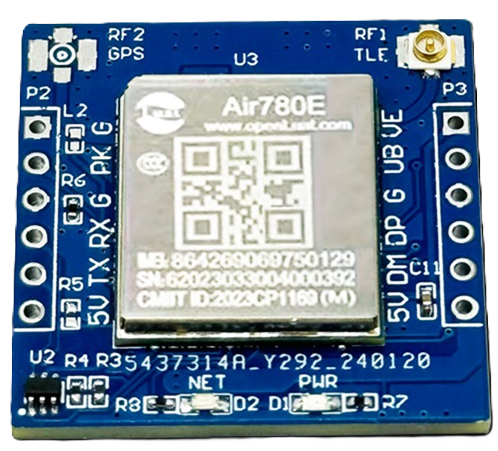
The Air780E LTE Cat‑1 Module is a compact and efficient cellular communication module designed for Internet of Things (IoT) applications. Manufactured under the part ID AIR780E LTE Cat-1 Communication Module, this device provides reliable wireless connectivity with low power consumption and high data rates. It is ideal for applications requiring remote monitoring, control, and data transmission.

Explore Projects Built with Air780E LTE Cat‑1 Module

Use Cirkit Designer to design, explore, and prototype these projects online. Some projects support real-time simulation. Click "Open Project" to start designing instantly!
Cellular-Enabled IoT Device with Real-Time Clock and Power Management
Image of LRCM PHASE 2 BASIC: A project utilizing Air780E LTE Cat‑1 Module in a practical application
This circuit features a LilyGo-SIM7000G module for cellular communication and GPS functionality, interfaced with an RTC DS3231 for real-time clock capabilities. It includes voltage sensing through two voltage sensor modules, and uses an 8-channel opto-coupler for isolating different parts of the circuit. Power management is handled by a buck converter connected to a DC power source and batteries, with a fuse for protection and a rocker switch for on/off control. Additionally, there's an LED for indication purposes.
Cirkit Designer LogoOpen Project in Cirkit Designer
ESP8266 NodeMCU with LoRa and RS-485 Communication and Ethernet Connectivity
Image of Wiring Diagram LoRa: A project utilizing Air780E LTE Cat‑1 Module in a practical application
This circuit serves as a multi-protocol communication hub featuring two ESP8266 NodeMCUs for processing, each connected to a LoRa Ra-02 SX1278 for long-range wireless communication. One NodeMCU is also connected to an RS-485 module for serial communication and a W5500 Ethernet module for network connectivity, with MB102 modules supplying power.
Cirkit Designer LogoOpen Project in Cirkit Designer
ESP32-Based Cellular and GPS Tracking System with User Interface
Image of Keychain Device: A project utilizing Air780E LTE Cat‑1 Module in a practical application
This circuit features an ESP32 microcontroller interfaced with a SIM 800L GSM module for cellular communication and a Neo 6M GPS module for location tracking. A voltage regulator is used to maintain a stable voltage supply from a polymer lithium-ion battery to the GSM, GPS, and ESP32 modules. Additionally, the circuit includes a pushbutton to trigger inputs and an LED with a current-limiting resistor, likely for status indication.
Cirkit Designer LogoOpen Project in Cirkit Designer
Satellite-Based Timing and Navigation System with SDR and Atomic Clock Synchronization
Image of GPS 시스템 측정 구성도_Confirm: A project utilizing Air780E LTE Cat‑1 Module in a practical application
This circuit appears to be a complex system involving power supply management, GPS and timing synchronization, and data communication. It includes a SI-TEX G1 Satellite Compass for GPS data, an XHTF1021 Atomic Rubidium Clock for precise timing, and Ettus USRP B200 units for software-defined radio communication. Power is supplied through various SMPS units and distributed via terminal blocks and DC jacks. Data communication is facilitated by Beelink MINI S12 N95 computers, RS232 splitters, and a 1000BASE-T Media Converter for network connectivity. RF Directional Couplers are used to interface antennas with the USRP units, and the entire system is likely contained within cases for protection and organization.
Cirkit Designer LogoOpen Project in Cirkit Designer

Explore Projects Built with Air780E LTE Cat‑1 Module

Use Cirkit Designer to design, explore, and prototype these projects online. Some projects support real-time simulation. Click "Open Project" to start designing instantly!
Image of LRCM PHASE 2 BASIC: A project utilizing Air780E LTE Cat‑1 Module in a practical application
Cellular-Enabled IoT Device with Real-Time Clock and Power Management
This circuit features a LilyGo-SIM7000G module for cellular communication and GPS functionality, interfaced with an RTC DS3231 for real-time clock capabilities. It includes voltage sensing through two voltage sensor modules, and uses an 8-channel opto-coupler for isolating different parts of the circuit. Power management is handled by a buck converter connected to a DC power source and batteries, with a fuse for protection and a rocker switch for on/off control. Additionally, there's an LED for indication purposes.
Cirkit Designer LogoOpen Project in Cirkit Designer
Image of Wiring Diagram LoRa: A project utilizing Air780E LTE Cat‑1 Module in a practical application
ESP8266 NodeMCU with LoRa and RS-485 Communication and Ethernet Connectivity
This circuit serves as a multi-protocol communication hub featuring two ESP8266 NodeMCUs for processing, each connected to a LoRa Ra-02 SX1278 for long-range wireless communication. One NodeMCU is also connected to an RS-485 module for serial communication and a W5500 Ethernet module for network connectivity, with MB102 modules supplying power.
Cirkit Designer LogoOpen Project in Cirkit Designer
Image of Keychain Device: A project utilizing Air780E LTE Cat‑1 Module in a practical application
ESP32-Based Cellular and GPS Tracking System with User Interface
This circuit features an ESP32 microcontroller interfaced with a SIM 800L GSM module for cellular communication and a Neo 6M GPS module for location tracking. A voltage regulator is used to maintain a stable voltage supply from a polymer lithium-ion battery to the GSM, GPS, and ESP32 modules. Additionally, the circuit includes a pushbutton to trigger inputs and an LED with a current-limiting resistor, likely for status indication.
Cirkit Designer LogoOpen Project in Cirkit Designer
Image of GPS 시스템 측정 구성도_Confirm: A project utilizing Air780E LTE Cat‑1 Module in a practical application
Satellite-Based Timing and Navigation System with SDR and Atomic Clock Synchronization
This circuit appears to be a complex system involving power supply management, GPS and timing synchronization, and data communication. It includes a SI-TEX G1 Satellite Compass for GPS data, an XHTF1021 Atomic Rubidium Clock for precise timing, and Ettus USRP B200 units for software-defined radio communication. Power is supplied through various SMPS units and distributed via terminal blocks and DC jacks. Data communication is facilitated by Beelink MINI S12 N95 computers, RS232 splitters, and a 1000BASE-T Media Converter for network connectivity. RF Directional Couplers are used to interface antennas with the USRP units, and the entire system is likely contained within cases for protection and organization.
Cirkit Designer LogoOpen Project in Cirkit Designer

Common Applications and Use Cases

  • Smart metering and utility monitoring
  • Asset tracking and fleet management
  • Industrial automation and control systems
  • Smart home devices and security systems
  • Environmental monitoring and agricultural IoT solutions

Technical Specifications

Key Technical Details

Parameter Specification
Cellular Technology LTE Cat-1
Frequency Bands LTE FDD: B1/B3/B5/B8
Data Rate Uplink: 5 Mbps, Downlink: 10 Mbps
Operating Voltage 3.3V to 4.2V
Power Consumption Idle: ~1.5mA, Active: ~300mA
Operating Temperature -40°C to +85°C
Dimensions 24mm x 24mm x 2.6mm
Interface UART, GPIO, ADC, I2C, SPI
Antenna Interface 50Ω impedance, external antenna required
Certifications CE, FCC, RoHS

Pin Configuration and Descriptions

The Air780E module has a total of 42 pins. Below is a summary of the key pins and their functions:

Pin Number Pin Name Description
1 VCC Power supply input (3.3V to 4.2V)
2 GND Ground
3 TXD UART Transmit
4 RXD UART Receive
5 RESET Reset input (active low)
6 PWRKEY Power-on key (active low)
7 GPIO1 General-purpose I/O
8 GPIO2 General-purpose I/O
9 ADC Analog-to-digital converter input
10 SPI_CLK SPI clock
11 SPI_MOSI SPI master-out, slave-in
12 SPI_MISO SPI master-in, slave-out
13 I2C_SCL I2C clock
14 I2C_SDA I2C data
15 ANT Antenna interface

For a complete pinout, refer to the manufacturer's datasheet.

Usage Instructions

How to Use the Air780E in a Circuit

  1. Power Supply: Connect the VCC pin to a regulated 3.3V to 4.2V power source and GND to ground.
  2. UART Communication: Use the TXD and RXD pins to interface with a microcontroller or PC for serial communication.
  3. Antenna Connection: Attach an external antenna to the ANT pin for optimal signal reception.
  4. Power-On Sequence:
    • Pull the PWRKEY pin low for at least 1 second to power on the module.
    • Wait for the module to initialize (indicated by UART responses or status LEDs, if available).
  5. Data Transmission:
    • Use AT commands over UART to configure the module and send/receive data.
    • Example AT commands include AT+CSQ (signal quality) and AT+CGATT (attach to network).

Important Considerations and Best Practices

  • Power Supply Stability: Ensure a stable power supply with minimal ripple to avoid module resets.
  • Antenna Placement: Position the antenna away from noise sources and metal objects for better signal quality.
  • Firmware Updates: Periodically check for firmware updates from the manufacturer to ensure optimal performance and security.
  • ESD Protection: Implement proper ESD protection on all external interfaces to prevent damage.

Example: Connecting to an Arduino UNO

The Air780E can be connected to an Arduino UNO via UART. Below is an example of how to send an AT command to the module:

Wiring Diagram

Air780E Pin Arduino UNO Pin
TXD RX (Pin 0)
RXD TX (Pin 1)
GND GND
VCC 3.3V
PWRKEY Digital Pin 7

Arduino Code Example

#include <SoftwareSerial.h>

// Define RX and TX pins for SoftwareSerial
SoftwareSerial air780e(10, 11); // RX = Pin 10, TX = Pin 11

void setup() {
  // Initialize serial communication with Air780E
  air780e.begin(9600); // Default baud rate for Air780E
  Serial.begin(9600);  // Serial monitor for debugging

  // Power on the Air780E module
  pinMode(7, OUTPUT);  // PWRKEY connected to Pin 7
  digitalWrite(7, LOW);
  delay(1000);         // Hold PWRKEY low for 1 second
  digitalWrite(7, HIGH);

  // Wait for the module to initialize
  delay(5000);
  Serial.println("Air780E initialized.");
}

void loop() {
  // Send an AT command to check signal quality
  air780e.println("AT+CSQ");
  delay(1000);

  // Read and print the response from the module
  while (air780e.available()) {
    char c = air780e.read();
    Serial.print(c);
  }
}

Troubleshooting and FAQs

Common Issues and Solutions

  1. Module Not Powering On:

    • Ensure the PWRKEY pin is held low for at least 1 second during power-on.
    • Verify the power supply voltage is within the 3.3V to 4.2V range.
  2. No Response to AT Commands:

    • Check the UART connections (TXD and RXD) and ensure they are not swapped.
    • Confirm the baud rate matches the module's default (9600 bps).
  3. Poor Signal Quality:

    • Verify the antenna is securely connected to the ANT pin.
    • Relocate the module to an area with better network coverage.
  4. Frequent Resets:

    • Check for power supply stability and ensure sufficient decoupling capacitors are used.

FAQs

Q: Can the Air780E operate on 5V logic levels?
A: No, the Air780E operates on 3.3V logic levels. Use a level shifter if interfacing with 5V systems.

Q: How do I update the firmware?
A: Firmware updates can be performed via the UART interface using the manufacturer's update tool. Refer to the official documentation for detailed instructions.

Q: What is the maximum data rate supported?
A: The Air780E supports a maximum uplink data rate of 5 Mbps and a downlink data rate of 10 Mbps.

Q: Is the module compatible with 2G networks?
A: No, the Air780E is designed specifically for LTE Cat-1 networks and does not support 2G connectivity.