How to Use Super Duty Actuators: Examples, Pinouts, and Specs
Introduction
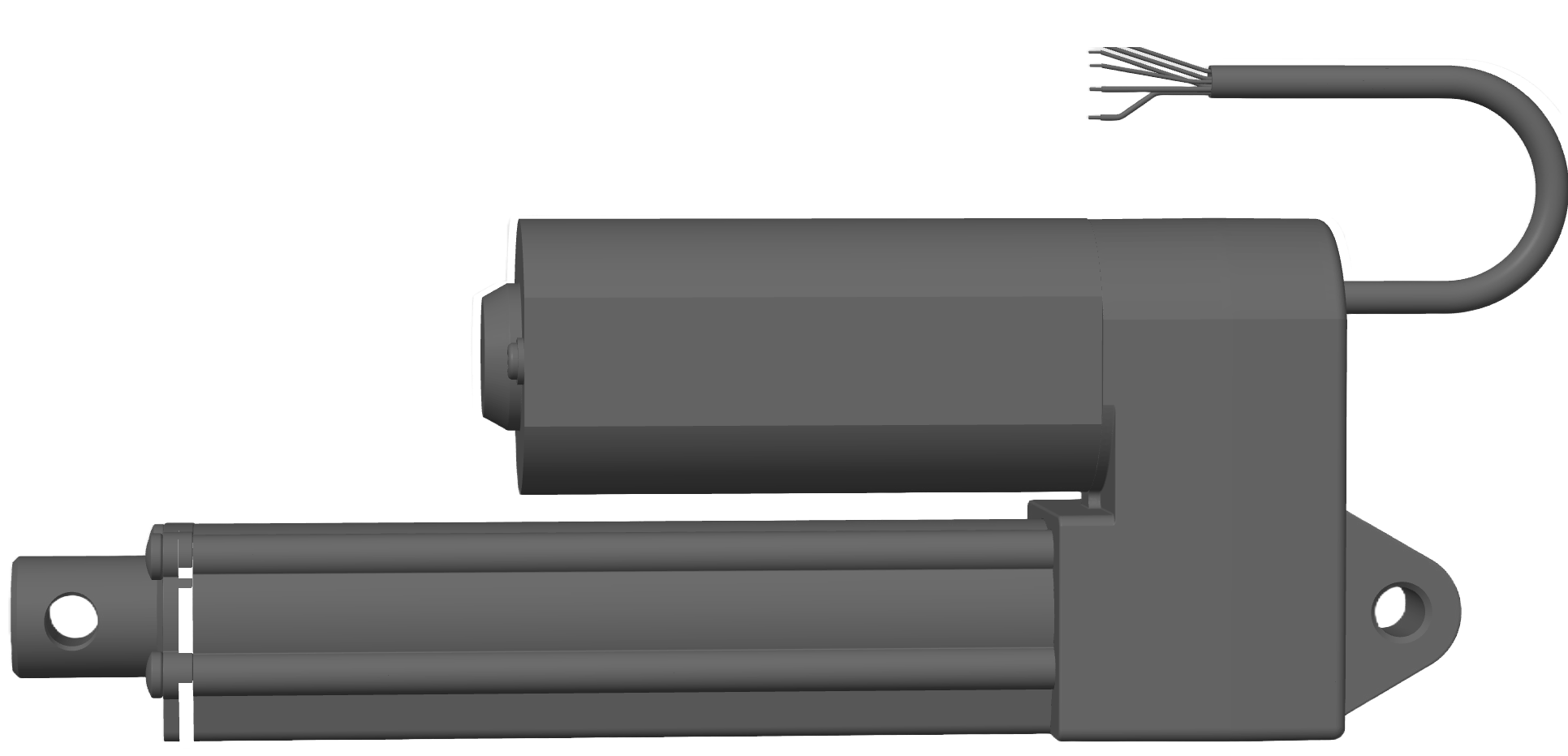
Super Duty Actuators, manufactured by Firgelli Automations (Part ID: F-SD-H-220-12v-XX), are robust devices designed to convert electrical energy into mechanical motion. These actuators are specifically engineered for heavy-duty applications requiring high torque, precision, and reliability. Their durable construction and high-performance capabilities make them ideal for use in industrial automation, robotics, agricultural machinery, and other demanding environments.
Explore Projects Built with Super Duty Actuators
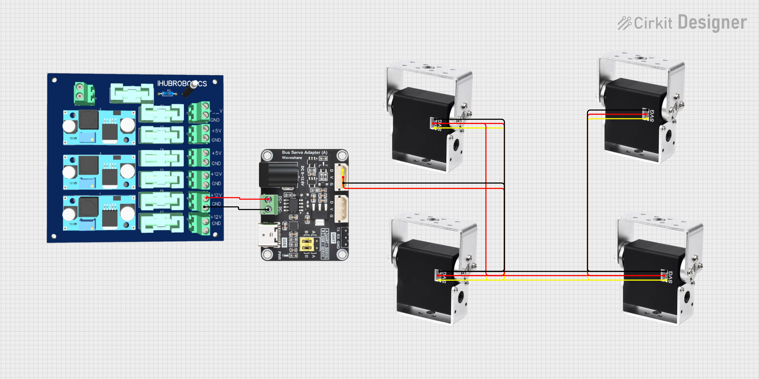
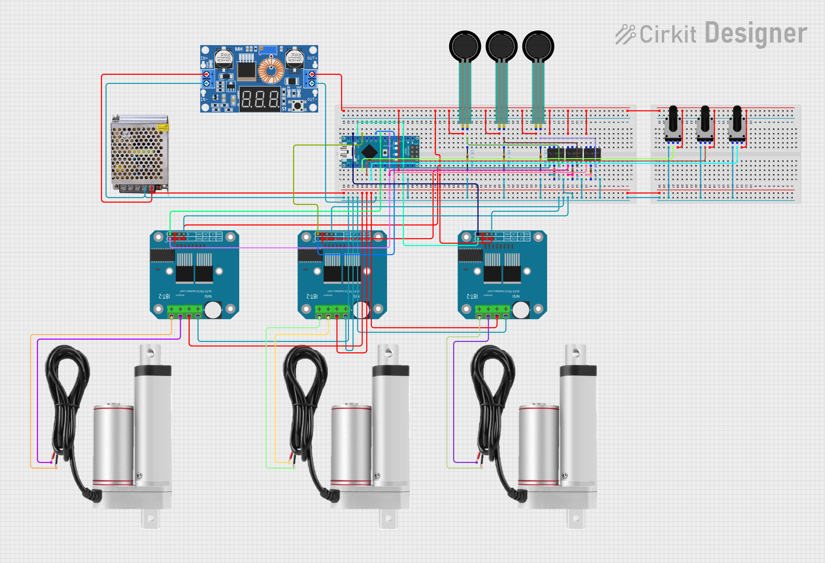
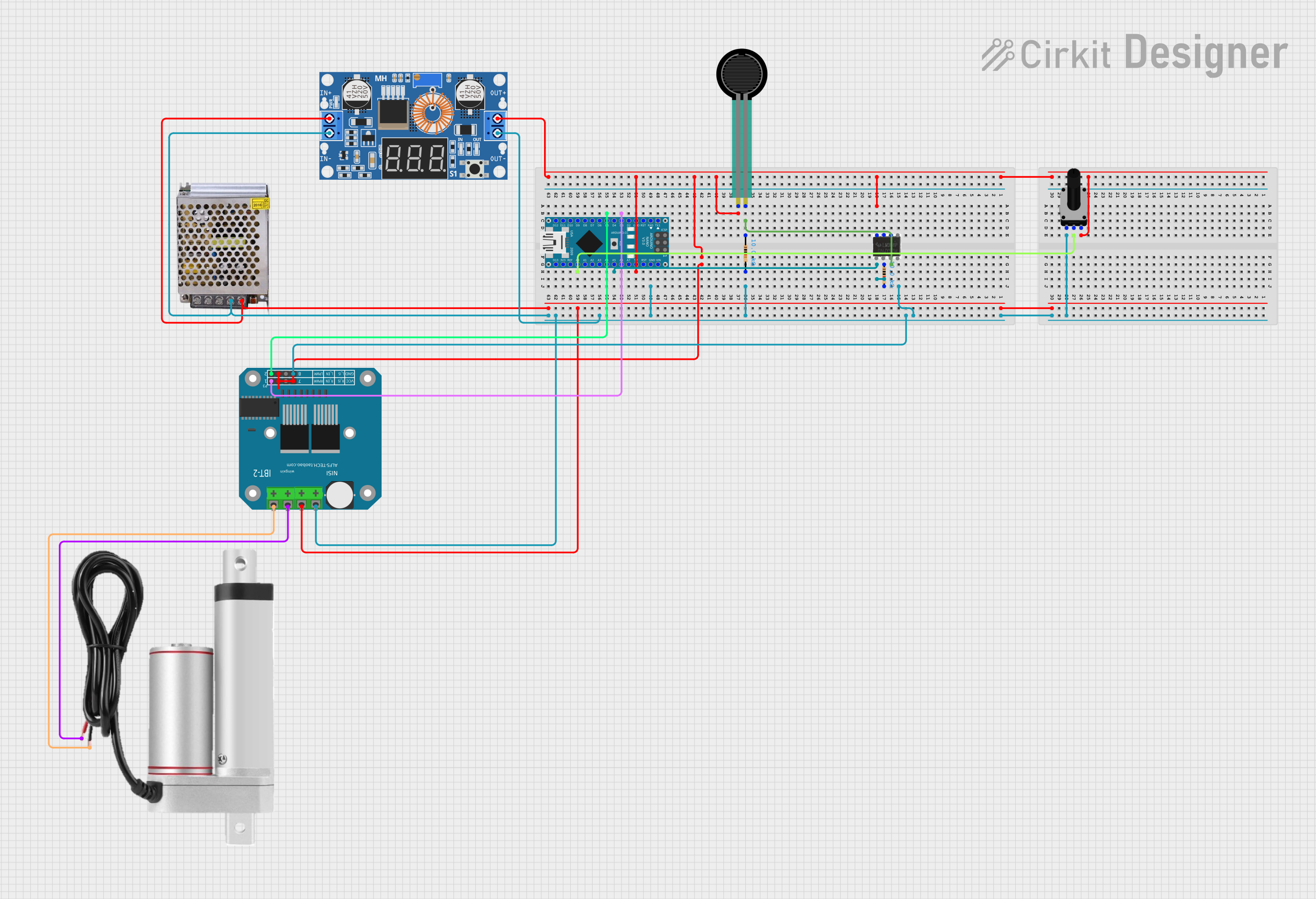
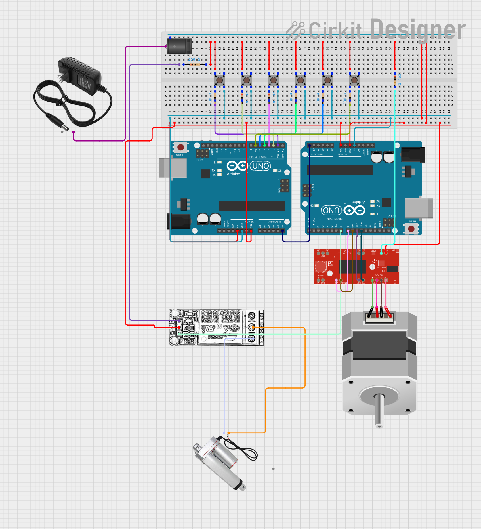
Explore Projects Built with Super Duty Actuators
Common Applications
- Industrial automation systems
- Robotic arms and manipulators
- Agricultural equipment
- Heavy machinery and construction tools
- Adjustable platforms and lifting mechanisms
Technical Specifications
Below are the key technical details for the Super Duty Actuators:
General Specifications
| Parameter | Value |
|---|---|
| Manufacturer | Firgelli Automations |
| Part ID | F-SD-H-220-12v-XX |
| Input Voltage | 12V DC |
| Maximum Load Capacity | 220 lbs (100 kg) |
| Stroke Length Options | Customizable (XX denotes length in mm) |
| Speed (No Load) | 0.5 in/sec (12.7 mm/sec) |
| Duty Cycle | 25% at full load |
| Operating Temperature | -26°C to +65°C (-15°F to +150°F) |
| Protection Rating | IP66 (dust-tight and water-resistant) |
Pin Configuration
The actuator typically comes with a 2-wire configuration for power and control. The pinout is as follows:
| Wire Color | Function | Description |
|---|---|---|
| Red | Positive (+) | Connect to the positive terminal of the power supply. |
| Black | Negative (-) | Connect to the negative terminal of the power supply. |
Usage Instructions
How to Use the Super Duty Actuator in a Circuit
- Power Supply: Ensure the actuator is powered by a 12V DC power source capable of supplying sufficient current for the load.
- Polarity Control: The actuator's direction of motion is controlled by reversing the polarity of the power supply:
- Positive voltage on the red wire and negative on the black wire will extend the actuator.
- Reversing the polarity will retract the actuator.
- Mounting: Securely mount the actuator using the provided brackets or custom mounting solutions. Ensure the actuator is aligned with the load to prevent binding or damage.
- Control Options:
- Use a DPDT (Double Pole Double Throw) switch for manual control.
- For automated control, integrate the actuator with a microcontroller (e.g., Arduino UNO) and an H-bridge motor driver.
Arduino UNO Example Code
Below is an example of how to control the Super Duty Actuator using an Arduino UNO and an L298N H-bridge motor driver:
// Arduino UNO code to control the Super Duty Actuator
// Ensure the actuator is connected to the L298N motor driver
// IN1 and IN2 control the actuator's direction

const int IN1 = 7; // L298N IN1 pin connected to Arduino pin 7
const int IN2 = 8; // L298N IN2 pin connected to Arduino pin 8

void setup() {
  pinMode(IN1, OUTPUT); // Set IN1 as output
  pinMode(IN2, OUTPUT); // Set IN2 as output
}

void loop() {
  // Extend the actuator
  digitalWrite(IN1, HIGH); // Set IN1 high
  digitalWrite(IN2, LOW);  // Set IN2 low
  delay(5000);             // Extend for 5 seconds

  // Stop the actuator
  digitalWrite(IN1, LOW);  // Set IN1 low
  digitalWrite(IN2, LOW);  // Set IN2 low
  delay(2000);             // Pause for 2 seconds

  // Retract the actuator
  digitalWrite(IN1, LOW);  // Set IN1 low
  digitalWrite(IN2, HIGH); // Set IN2 high
  delay(5000);             // Retract for 5 seconds

  // Stop the actuator
  digitalWrite(IN1, LOW);  // Set IN1 low
  digitalWrite(IN2, LOW);  // Set IN2 low
  delay(2000);             // Pause for 2 seconds
}
Important Considerations
- Current Rating: Ensure the power supply and motor driver can handle the actuator's current requirements under load.
- Duty Cycle: Operate the actuator within its 25% duty cycle to prevent overheating and damage.
- Alignment: Misalignment during installation can cause excessive wear or failure.
- Environmental Conditions: The IP66 rating ensures protection against dust and water, but avoid submerging the actuator.
Troubleshooting and FAQs
Common Issues and Solutions
Actuator Does Not Move:
- Cause: Insufficient power supply or incorrect wiring.
- Solution: Verify the power supply voltage and current. Check the wiring for proper connections.
Actuator Moves in One Direction Only:
- Cause: Faulty polarity control or damaged motor driver.
- Solution: Test the motor driver and ensure proper polarity switching.
Overheating:
- Cause: Exceeding the duty cycle or operating under excessive load.
- Solution: Reduce the load or operating time. Allow the actuator to cool down.
Unusual Noise or Vibration:
- Cause: Misalignment or mechanical obstruction.
- Solution: Inspect the mounting and ensure the actuator is aligned with the load.
FAQs
Can the actuator be used outdoors? Yes, the IP66 rating ensures it is suitable for outdoor use, but avoid prolonged submersion.
What is the maximum stroke length available? The stroke length is customizable. Contact Firgelli Automations for specific options.
Can I control the actuator with a PWM signal? Yes, you can use a PWM signal with a motor driver to control the speed and position of the actuator.
What happens if I exceed the duty cycle? Exceeding the duty cycle may cause the actuator to overheat and reduce its lifespan. Always adhere to the specified duty cycle.