How to Use Raspberry pi 3b+: Examples, Pinouts, and Specs
Introduction
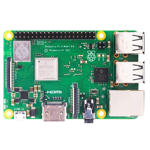
The Raspberry Pi 3 Model B+ is a small, affordable computer designed for a variety of electronics projects. It features a quad-core ARM Cortex-A53 CPU, 1GB RAM, and various I/O options including USB, HDMI, and GPIO pins. This versatile device is ideal for applications ranging from simple educational projects to complex IoT systems.
Explore Projects Built with Raspberry pi 3b+
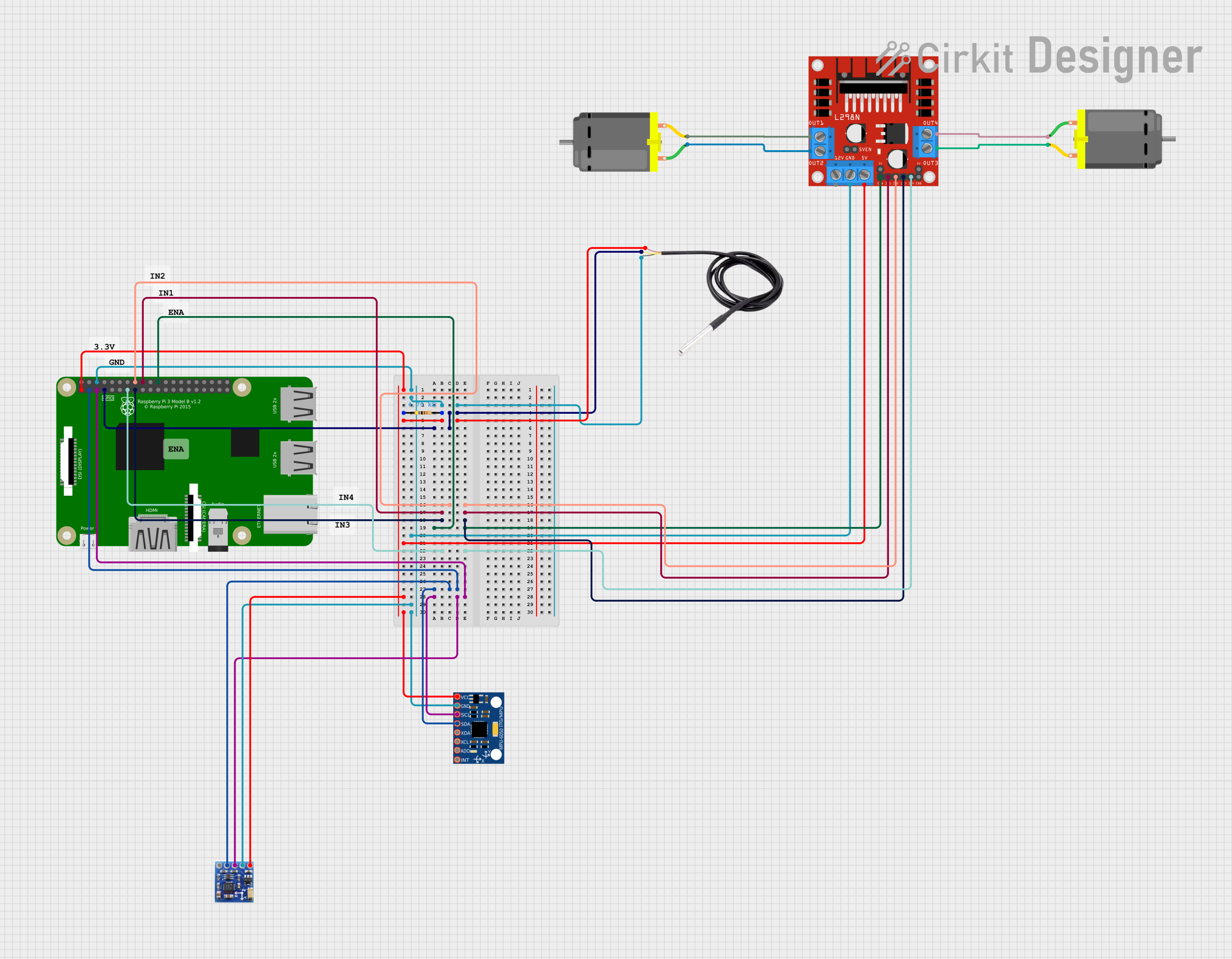
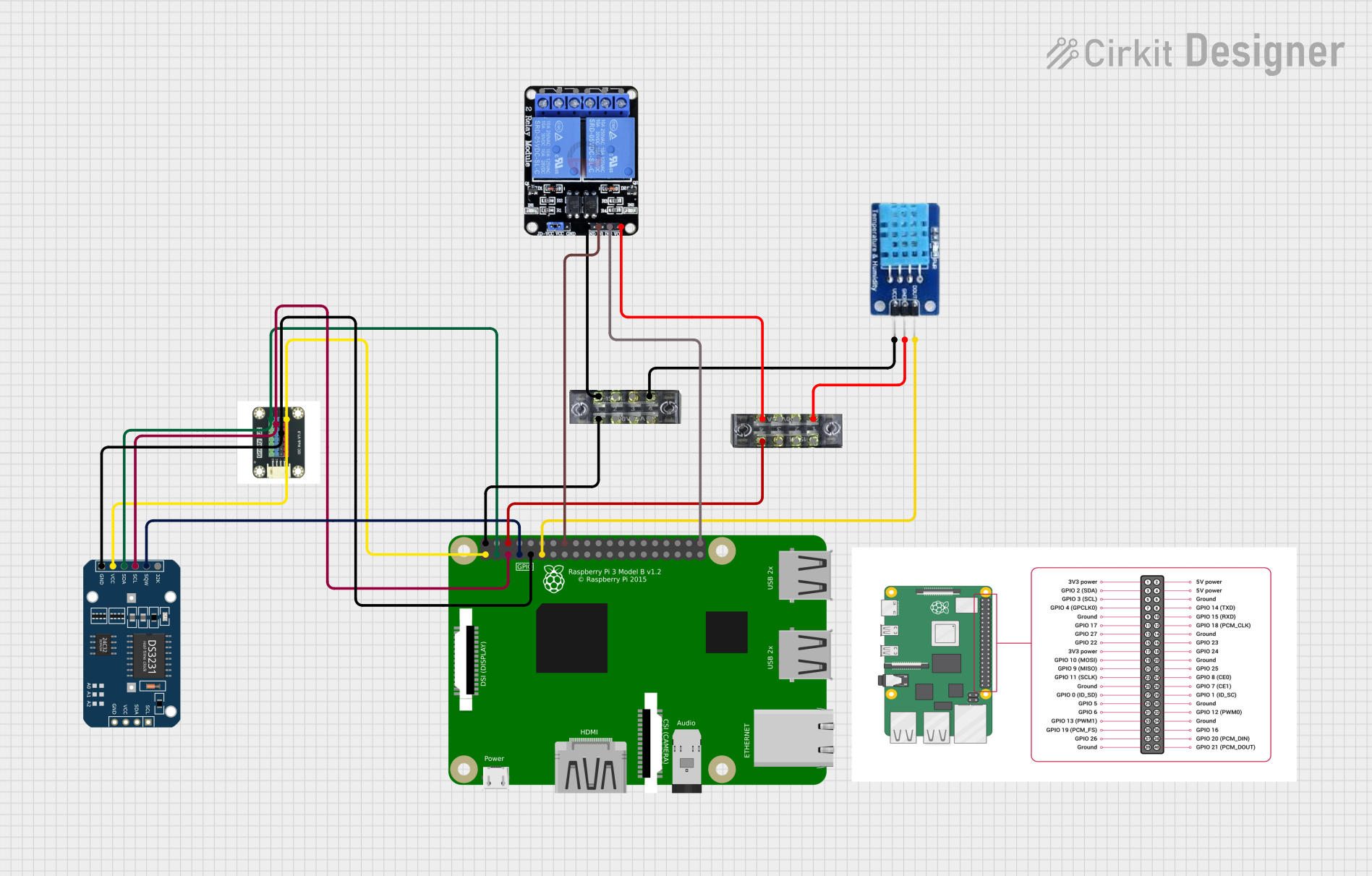
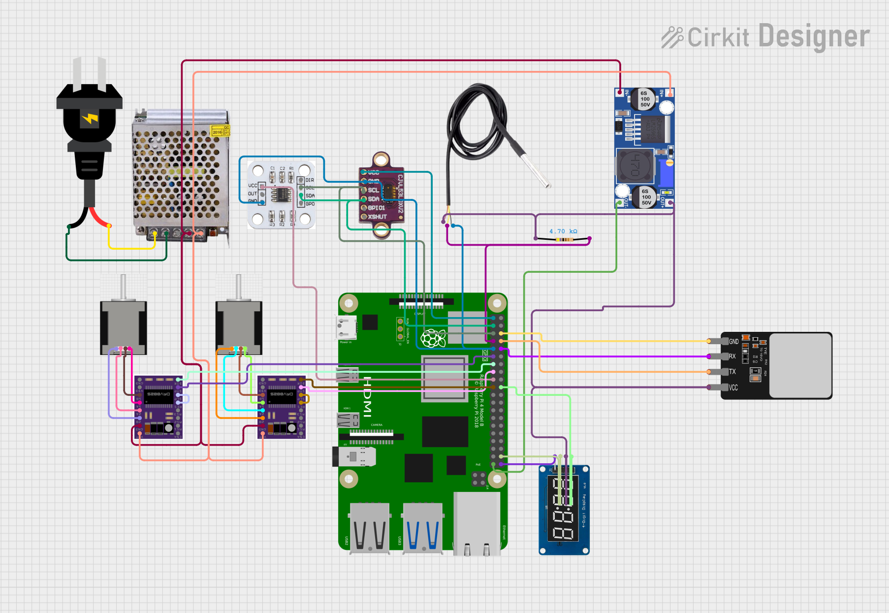
Explore Projects Built with Raspberry pi 3b+
Common Applications and Use Cases
- Educational Projects: Ideal for learning programming and electronics.
- Home Automation: Control home devices and systems.
- Media Centers: Stream and play media content.
- IoT Projects: Connect and control various IoT devices.
- Robotics: Power and control robots and other automated systems.
Technical Specifications
Key Technical Details
| Specification | Details |
|---|---|
| CPU | Quad-core ARM Cortex-A53 |
| RAM | 1GB LPDDR2 SDRAM |
| USB Ports | 4 x USB 2.0 |
| HDMI | Full-size HDMI |
| Ethernet | Gigabit Ethernet over USB 2.0 (300 Mbps max) |
| Wireless | 2.4GHz and 5GHz IEEE 802.11.b/g/n/ac |
| Bluetooth | Bluetooth 4.2, BLE |
| GPIO Pins | 40-pin header |
| Power Supply | 5V/2.5A DC via micro USB connector |
| Operating System | Raspbian, Ubuntu, and other Linux distros |
Pin Configuration and Descriptions
The Raspberry Pi 3 Model B+ features a 40-pin GPIO header. Below is the pin configuration:
| Pin Number | Name | Description |
|---|---|---|
| 1 | 3.3V | 3.3V Power |
| 2 | 5V | 5V Power |
| 3 | GPIO2 | SDA1, I2C |
| 4 | 5V | 5V Power |
| 5 | GPIO3 | SCL1, I2C |
| 6 | GND | Ground |
| 7 | GPIO4 | GPCLK0 |
| 8 | GPIO14 | TXD0 |
| 9 | GND | Ground |
| 10 | GPIO15 | RXD0 |
| 11 | GPIO17 | General Purpose I/O |
| 12 | GPIO18 | PCM_CLK |
| 13 | GPIO27 | General Purpose I/O |
| 14 | GND | Ground |
| 15 | GPIO22 | General Purpose I/O |
| 16 | GPIO23 | General Purpose I/O |
| 17 | 3.3V | 3.3V Power |
| 18 | GPIO24 | General Purpose I/O |
| 19 | GPIO10 | SPI_MOSI |
| 20 | GND | Ground |
| 21 | GPIO9 | SPI_MISO |
| 22 | GPIO25 | General Purpose I/O |
| 23 | GPIO11 | SPI_CLK |
| 24 | GPIO8 | SPI_CE0_N |
| 25 | GND | Ground |
| 26 | GPIO7 | SPI_CE1_N |
| 27 | ID_SD | I2C ID EEPROM |
| 28 | ID_SC | I2C ID EEPROM |
| 29 | GPIO5 | General Purpose I/O |
| 30 | GND | Ground |
| 31 | GPIO6 | General Purpose I/O |
| 32 | GPIO12 | PWM0 |
| 33 | GPIO13 | PWM1 |
| 34 | GND | Ground |
| 35 | GPIO19 | PCM_FS |
| 36 | GPIO16 | General Purpose I/O |
| 37 | GPIO26 | General Purpose I/O |
| 38 | GPIO20 | PCM_DIN |
| 39 | GND | Ground |
| 40 | GPIO21 | PCM_DOUT |
Usage Instructions
How to Use the Component in a Circuit
Power Supply:
- Connect a 5V/2.5A DC power supply to the micro USB connector.
Connecting Peripherals:
- Connect a monitor via the HDMI port.
- Attach a keyboard and mouse to the USB ports.
Network Connection:
- Use the Ethernet port for wired network connections.
- Alternatively, connect to a Wi-Fi network using the built-in wireless module.
GPIO Usage:
- Use the GPIO pins to connect sensors, LEDs, and other components.
- Ensure proper pin configuration to avoid damage.
Important Considerations and Best Practices
- Power Supply: Always use a reliable 5V/2.5A power supply to avoid power issues.
- Static Electricity: Handle the Raspberry Pi with care to avoid static electricity damage.
- Cooling: Consider using a heat sink or fan for cooling during intensive tasks.
- Software Updates: Regularly update the operating system and software to ensure security and performance.
Troubleshooting and FAQs
Common Issues Users Might Face
No Display Output:
- Ensure the HDMI cable is properly connected.
- Check if the monitor is set to the correct input source.
- Verify that the Raspberry Pi is powered on.
Wi-Fi Connection Problems:
- Ensure the Wi-Fi credentials are correct.
- Check if the Wi-Fi network is within range.
- Restart the Raspberry Pi and the router.
Overheating:
- Use a heat sink or fan to cool the Raspberry Pi.
- Ensure proper ventilation around the device.
Solutions and Tips for Troubleshooting
Power Issues:
- Use a reliable power supply.
- Check the power cable for any damage.
Software Problems:
- Reinstall the operating system if necessary.
- Use the
dmesgcommand to check for system errors.
Example Code for GPIO Control with Arduino UNO
// Example code to control an LED connected to GPIO pin 17 on the Raspberry Pi
// using an Arduino UNO

// Define the pin number
const int ledPin = 17;

void setup() {
  // Initialize the GPIO pin as an output
  pinMode(ledPin, OUTPUT);
}

void loop() {
  // Turn the LED on
  digitalWrite(ledPin, HIGH);
  delay(1000); // Wait for 1 second

  // Turn the LED off
  digitalWrite(ledPin, LOW);
  delay(1000); // Wait for 1 second
}
This documentation provides a comprehensive guide to using the Raspberry Pi 3 Model B+ for various electronics projects. Whether you are a beginner or an experienced user, this guide will help you get the most out of your Raspberry Pi.