How to Use HC-SR04 (SIM TEST): Examples, Pinouts, and Specs
HC-SR04 Ultrasonic Distance Sensor Documentation
1. Introduction
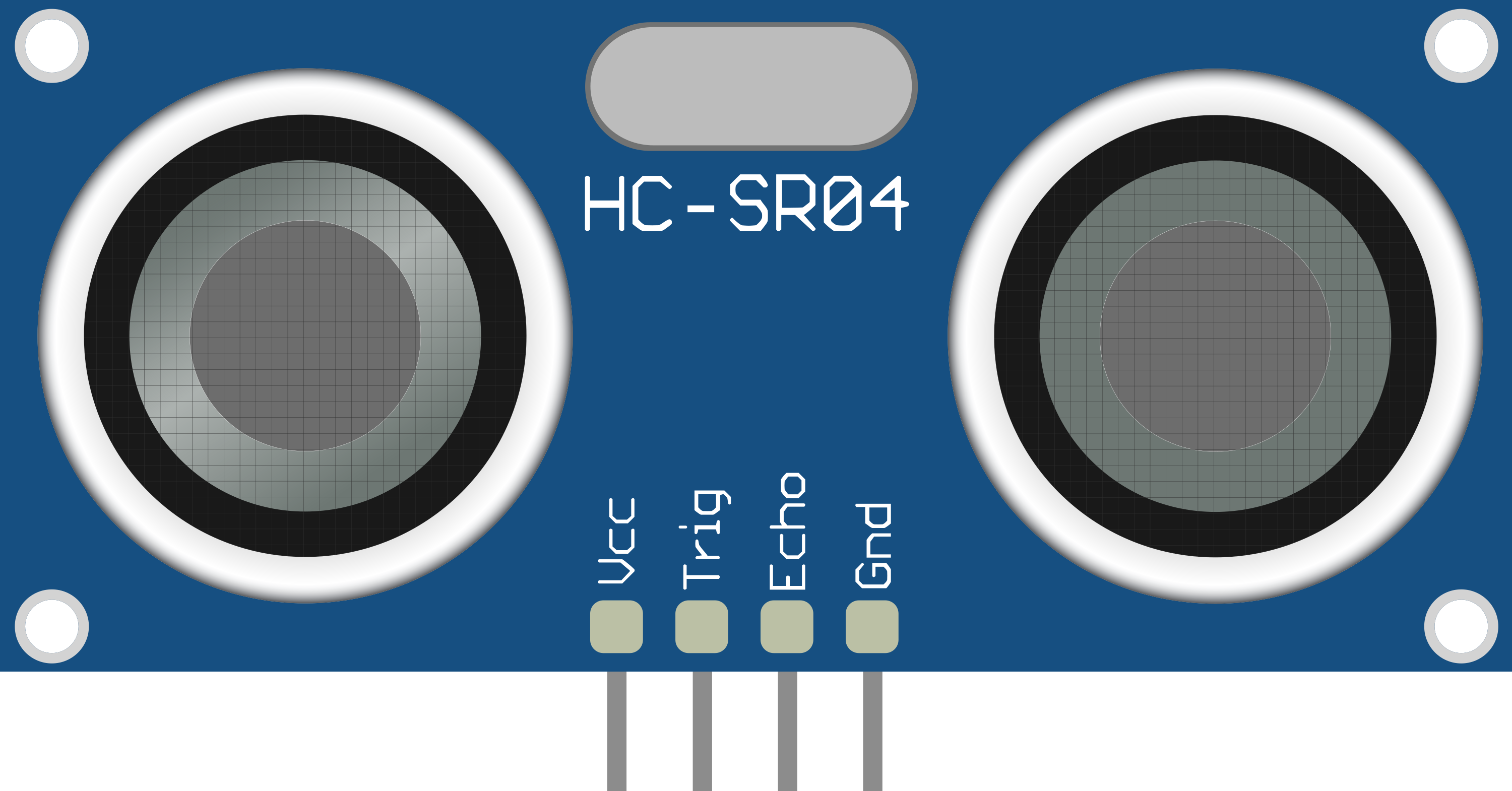
The HC-SR04 is an ultrasonic distance sensor that measures the distance to an object by emitting ultrasonic waves and calculating the time it takes for the echo to return. This sensor is widely used in robotics and automation for applications such as obstacle detection, distance measurement, and level sensing. Its ability to provide accurate distance readings makes it a popular choice for projects involving autonomous vehicles, drones, and various other electronic devices.
Common Applications and Use Cases
- Obstacle detection in robotics
- Distance measurement for automation systems
- Level sensing in tanks and containers
- Proximity sensing in smart home devices
- Object avoidance in mobile robots
2. Technical Specifications
Key Technical Details
| Specification | Value |
|---|---|
| Operating Voltage | 5V DC |
| Current Consumption | 15 mA (max) |
| Frequency | 40 kHz |
| Measuring Range | 2 cm to 400 cm |
| Accuracy | ±3 mm |
| Beam Angle | 15 degrees |
Pin Configuration and Descriptions
| Pin Number | Pin Name | Description |
|---|---|---|
| 1 | VCC | Power supply (5V) |
| 2 | Trig | Trigger pin for initiating measurement |
| 3 | Echo | Echo pin for receiving the reflected signal |
| 4 | GND | Ground connection |
3. Usage Instructions
How to Use the HC-SR04 in a Circuit
Wiring the Sensor:
- Connect the VCC pin to a 5V power supply.
- Connect the GND pin to the ground.
- Connect the Trig pin to a digital output pin on your microcontroller (e.g., Arduino).
- Connect the Echo pin to a digital input pin on your microcontroller.
Basic Circuit Diagram:
+5V ---- VCC (HC-SR04)
GND ---- GND (HC-SR04)
D2  ---- Trig (HC-SR04)
D3  ---- Echo (HC-SR04)
Important Considerations and Best Practices
- Ensure that the sensor is mounted securely and is not obstructed by any objects.
- Avoid using the sensor in environments with high levels of noise, as this can affect accuracy.
- The sensor should not be used in heavy rain or extreme temperatures, as this may damage it.
- Always check the wiring before powering the circuit to prevent damage.
4. Example Code for Arduino UNO
Here is a simple example code to use the HC-SR04 with an Arduino UNO:
#define TRIG_PIN 2  // Trigger pin connected to digital pin 2
#define ECHO_PIN 3  // Echo pin connected to digital pin 3

void setup() {
  Serial.begin(9600); // Start serial communication
  pinMode(TRIG_PIN, OUTPUT); // Set trigger pin as output
  pinMode(ECHO_PIN, INPUT);  // Set echo pin as input
}

void loop() {
  long duration, distance;

  // Clear the trigger
  digitalWrite(TRIG_PIN, LOW);
  delayMicroseconds(2);

  // Set the trigger high for 10 microseconds
  digitalWrite(TRIG_PIN, HIGH);
  delayMicroseconds(10);
  digitalWrite(TRIG_PIN, LOW);

  // Read the echo pin, return the sound wave travel time
  duration = pulseIn(ECHO_PIN, HIGH);

  // Calculate the distance (duration/2) * speed of sound (0.034 cm/us)
  distance = (duration * 0.034) / 2;

  // Print the distance to the Serial Monitor
  Serial.print("Distance: ");
  Serial.print(distance);
  Serial.println(" cm");

  delay(1000); // Wait for a second before the next measurement
}
5. Troubleshooting and FAQs
Common Issues Users Might Face
Inaccurate Distance Readings:
- Ensure the sensor is not obstructed and is mounted correctly.
- Check for any noise interference in the environment.
No Response from the Sensor:
- Verify the wiring connections and ensure the power supply is correct.
- Check if the Arduino code is uploaded correctly.
Sensor Not Powering On:
- Confirm that the VCC pin is connected to a 5V power source.
- Inspect for any physical damage to the sensor.
Solutions and Tips for Troubleshooting
- Always use a multimeter to check voltage levels at the VCC and GND pins.
- If using a breadboard, ensure that all connections are secure and not loose.
- Test the sensor with a simple code to isolate issues related to the sensor itself.
By following this documentation, users can effectively utilize the HC-SR04 ultrasonic distance sensor in their projects, ensuring accurate distance measurements and reliable performance.
Explore Projects Built with HC-SR04 (SIM TEST)
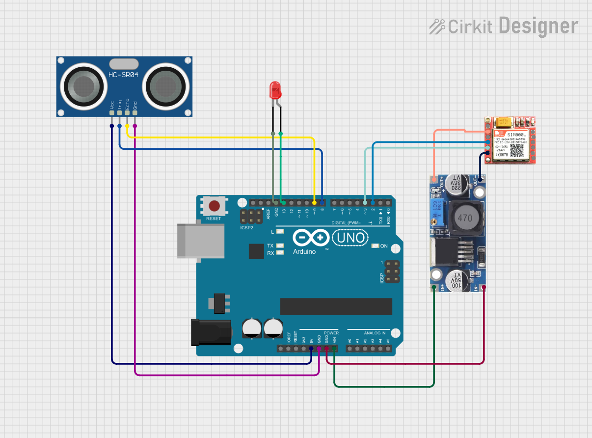

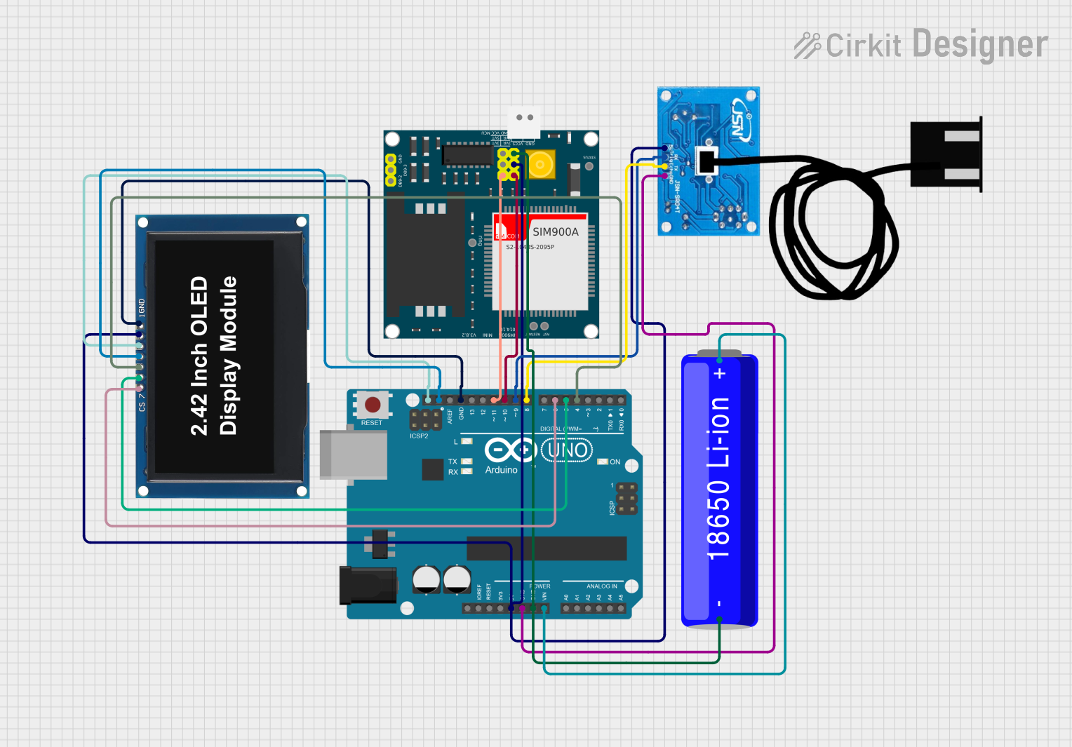
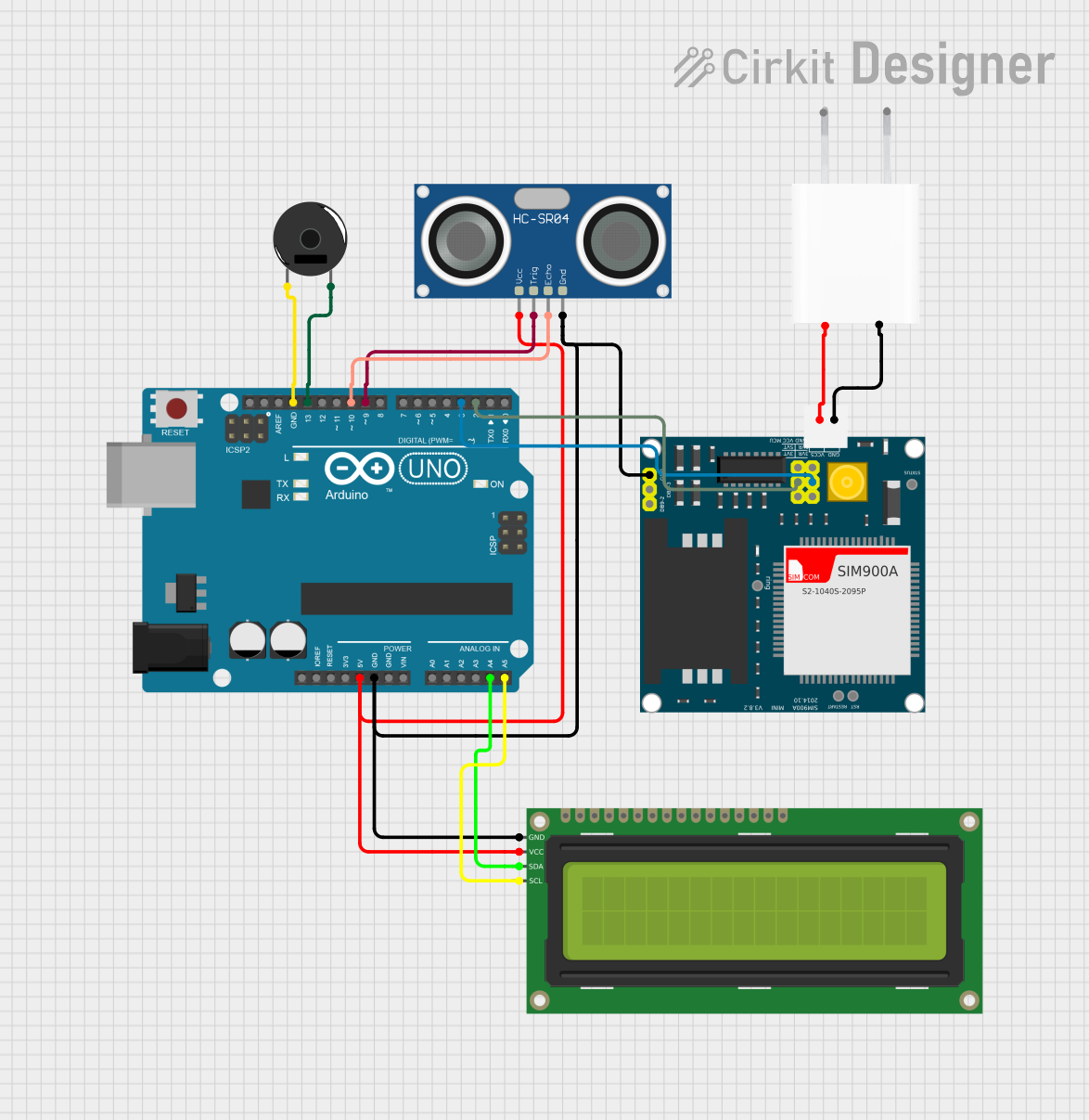
Explore Projects Built with HC-SR04 (SIM TEST)