
How to Use DC to AC Inverter: Examples, Pinouts, and Specs
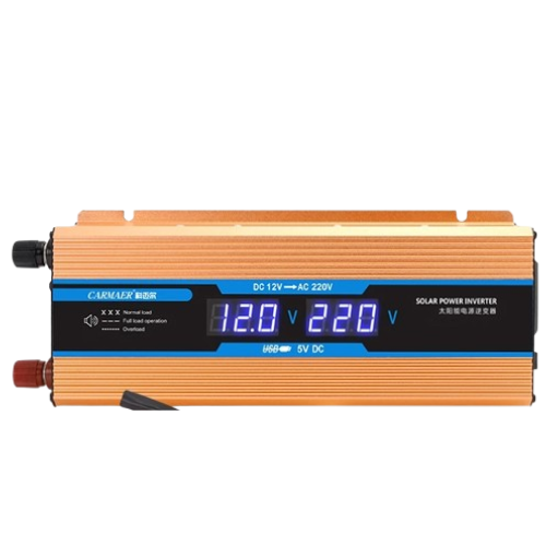
 Design with DC to AC Inverter in Cirkit Designer
Introduction
A DC to AC inverter is an electronic device that converts direct current (DC) into alternating current (AC). This conversion allows DC power sources, such as batteries or solar panels, to power AC devices like household appliances, tools, and lighting systems. Inverters are essential in renewable energy systems, uninterruptible power supplies (UPS), and portable power solutions.
Explore Projects Built with DC to AC Inverter
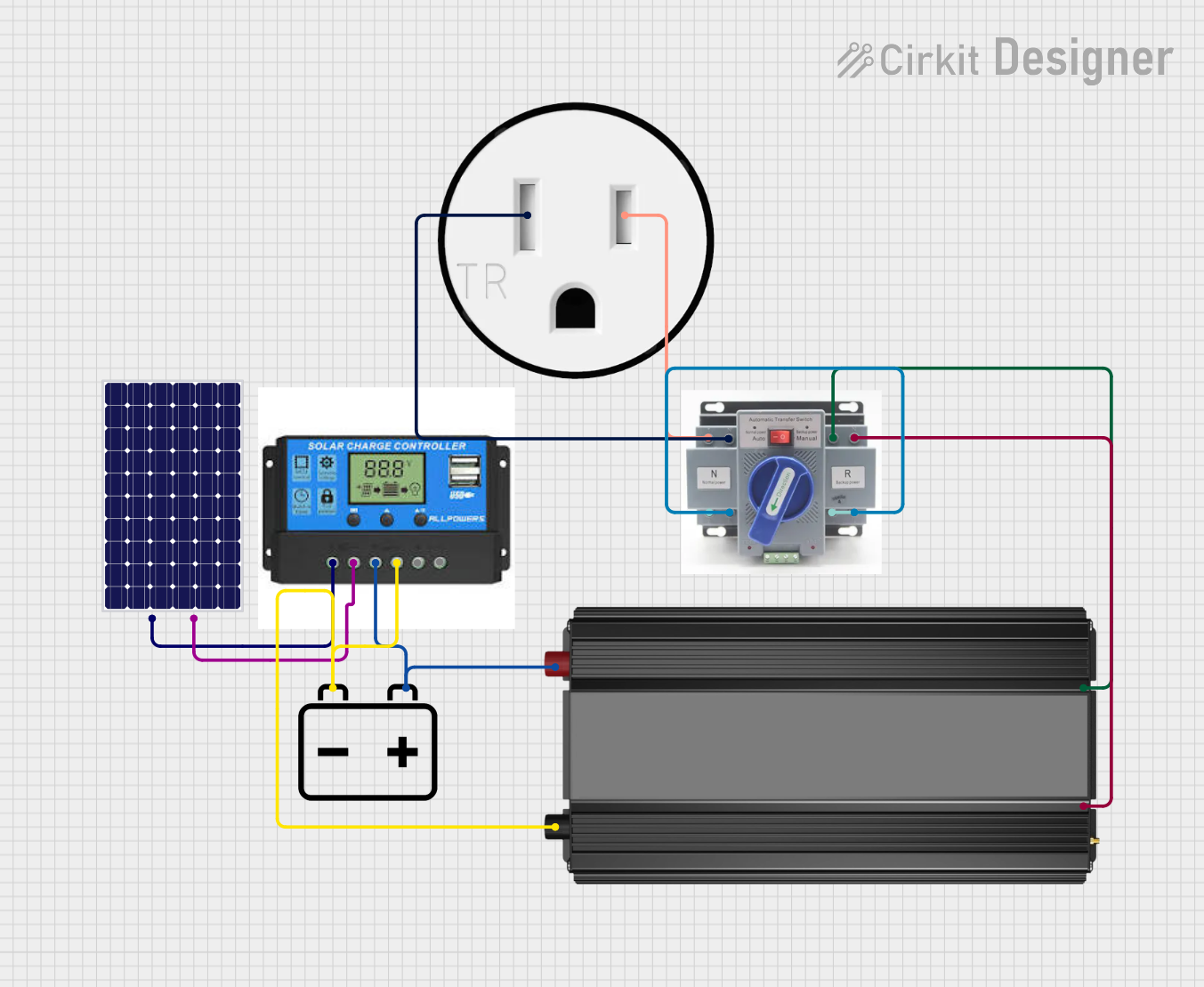 Open Project in Cirkit Designer
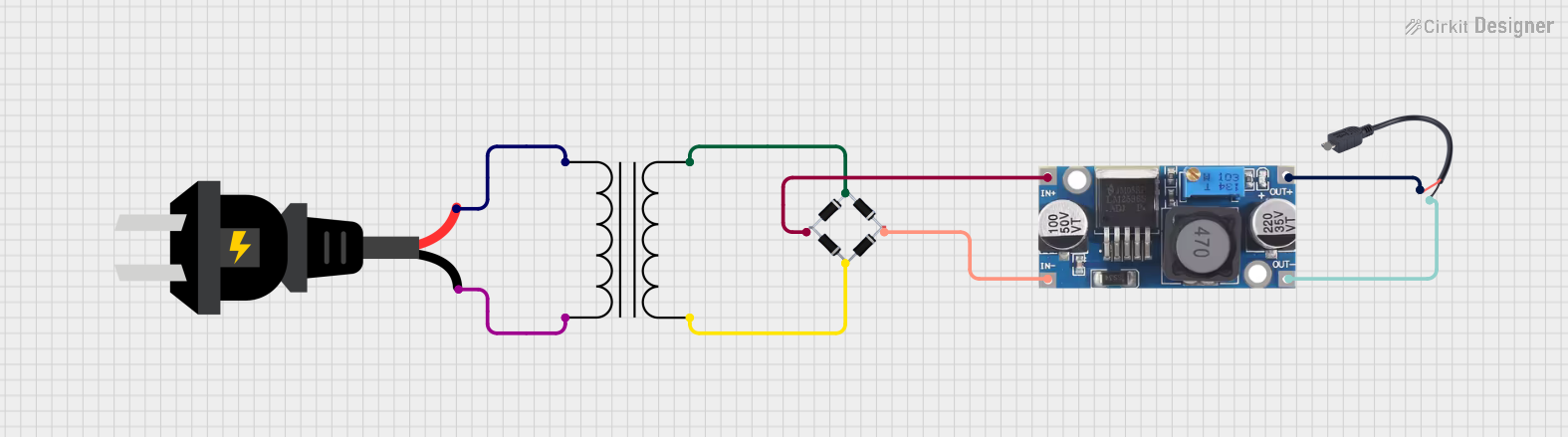 Open Project in Cirkit Designer
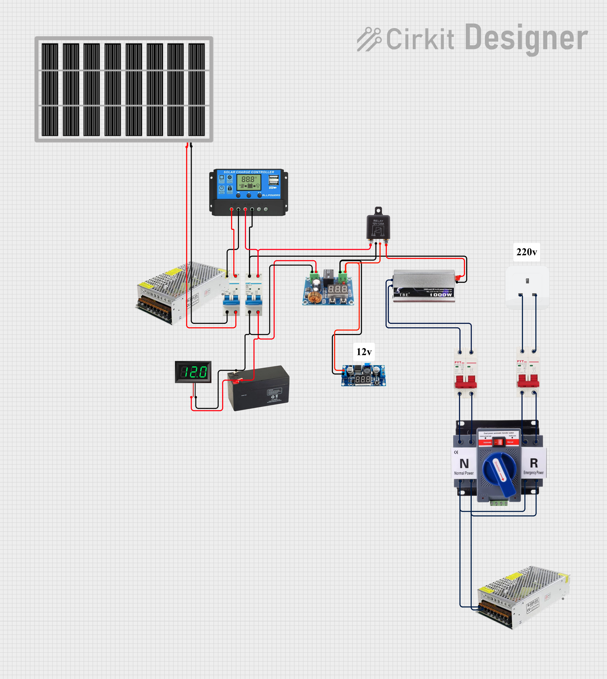 Open Project in Cirkit Designer
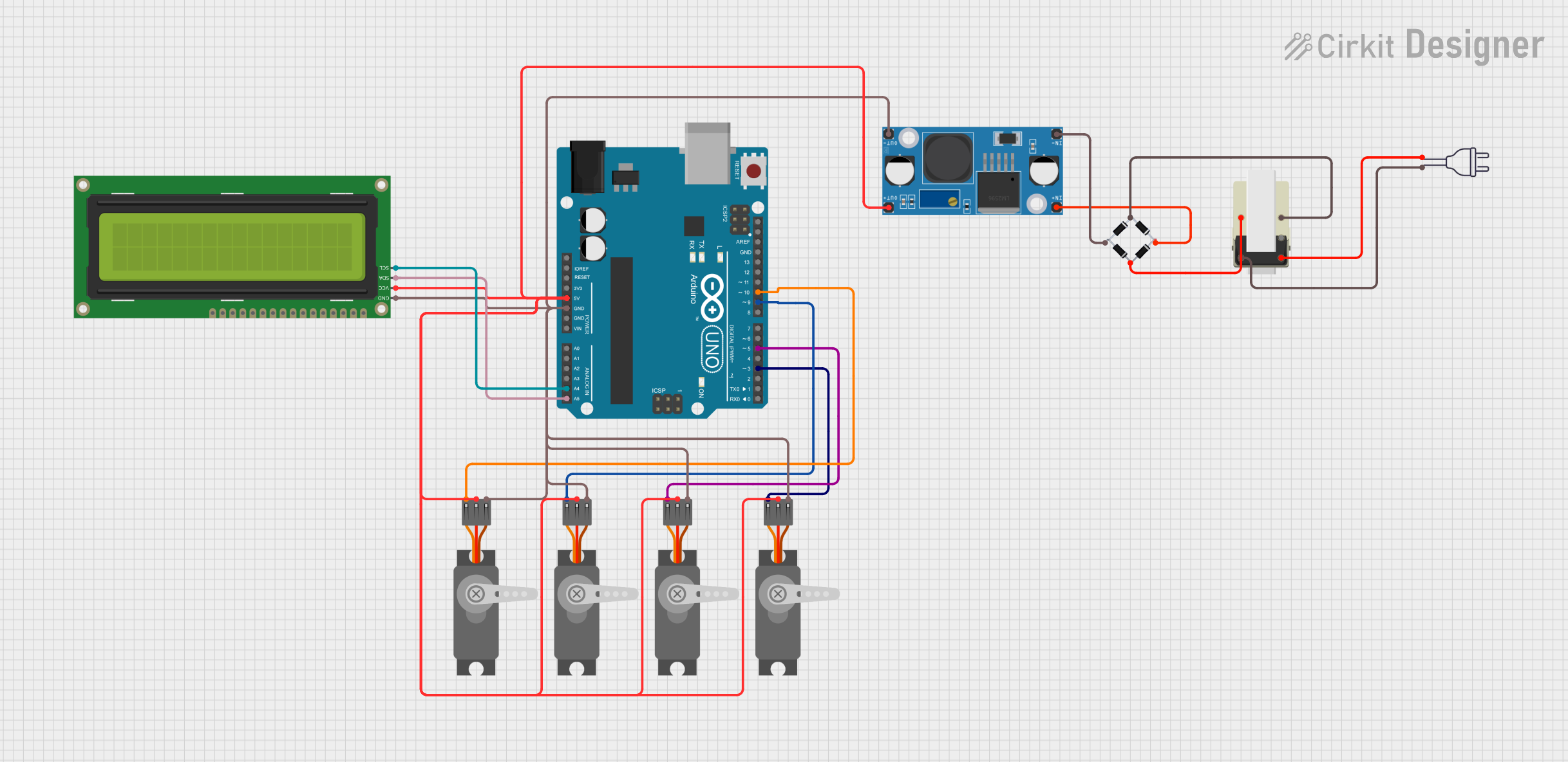 Open Project in Cirkit Designer
Explore Projects Built with DC to AC Inverter
Open Project in Cirkit DesignerOpen Project in Cirkit DesignerOpen Project in Cirkit DesignerOpen Project in Cirkit DesignerCommon Applications and Use Cases
- Solar power systems to convert DC from solar panels into AC for home use.
- Backup power systems (UPS) to provide AC power during outages.
- Portable power stations for camping or remote work.
- Electric vehicles to power AC accessories.
- Industrial and commercial applications requiring AC power from DC sources.
Technical Specifications
Below are the general technical specifications for a typical DC to AC inverter. Note that specific models may vary, so always refer to the manufacturer's datasheet for precise details.
Key Technical Details
- Input Voltage Range: 12V DC, 24V DC, or 48V DC (depending on the model)
- Output Voltage: 110V AC or 220V AC (region-specific)
- Output Frequency: 50Hz or 60Hz
- Output Waveform: Pure sine wave, modified sine wave, or square wave
- Efficiency: 85%–95% (depending on load and design)
- Power Rating: 100W to several kilowatts
- Protection Features: Overload, short circuit, over-temperature, and low battery protection
Pin Configuration and Descriptions
The pin configuration for a DC to AC inverter typically includes input and output terminals. Below is a table summarizing the connections:
| Pin/Terminal | Description |
|---|---|
| DC Input (+) | Positive terminal for connecting the DC power source (e.g., battery positive). |
| DC Input (-) | Negative terminal for connecting the DC power source (e.g., battery negative). |
| AC Output (L) | Live (hot) terminal for AC output. |
| AC Output (N) | Neutral terminal for AC output. |
| Ground (GND) | Ground terminal for safety and EMI reduction. |
Usage Instructions
How to Use the Component in a Circuit
Connect the DC Input:
- Ensure the DC power source matches the inverter's input voltage rating (e.g., 12V, 24V).
- Connect the positive terminal of the DC source to the inverter's DC Input (+) terminal.
- Connect the negative terminal of the DC source to the inverter's DC Input (-) terminal.
Connect the AC Load:
- Plug the AC device or appliance into the inverter's AC output socket or connect it to the AC Output (L) and (N) terminals.
- Ensure the load does not exceed the inverter's power rating.
Power On the Inverter:
- Turn on the inverter using its power switch or control mechanism.
- Verify that the AC output voltage and frequency match the requirements of the connected load.
Monitor Operation:
- Use the inverter's built-in indicators (if available) to monitor input voltage, output power, and fault conditions.
Important Considerations and Best Practices
- Match Voltage Ratings: Always ensure the DC input voltage matches the inverter's specifications.
- Avoid Overloading: Do not connect loads exceeding the inverter's power rating to prevent damage.
- Use Proper Wiring: Use appropriately rated wires for both DC input and AC output connections.
- Ventilation: Place the inverter in a well-ventilated area to prevent overheating.
- Grounding: Properly ground the inverter to ensure safety and reduce electromagnetic interference (EMI).
- Battery Protection: Use a fuse or circuit breaker between the battery and inverter to protect against overcurrent.
Example: Connecting to an Arduino UNO
While DC to AC inverters are not directly controlled by microcontrollers like the Arduino UNO, you can use an Arduino to monitor or control the inverter indirectly. For example, you can use a relay module to switch the inverter on or off based on certain conditions.
// Example Arduino code to control a DC to AC inverter using a relay module
const int relayPin = 7; // Pin connected to the relay module

void setup() {
  pinMode(relayPin, OUTPUT); // Set relay pin as output
  digitalWrite(relayPin, LOW); // Ensure relay is off at startup
}

void loop() {
  // Example condition: Turn on the inverter for 10 seconds
  digitalWrite(relayPin, HIGH); // Turn on the relay (and inverter)
  delay(10000); // Keep inverter on for 10 seconds
  digitalWrite(relayPin, LOW); // Turn off the relay (and inverter)
  delay(5000); // Wait for 5 seconds before repeating
}
Note: Ensure the relay module is rated for the inverter's power requirements and isolate the Arduino from high-voltage AC circuits.
Troubleshooting and FAQs
Common Issues and Solutions
| Issue | Possible Cause | Solution |
|---|---|---|
| Inverter does not turn on | Insufficient DC input voltage | Check the battery voltage and connections. Ensure it matches the inverter's input rating. |
| AC output is unstable or noisy | Overloaded inverter or poor grounding | Reduce the load or ensure proper grounding. |
| Inverter shuts down unexpectedly | Over-temperature or low battery protection | Allow the inverter to cool or recharge the battery. |
| Connected device does not work | Incompatible output waveform (e.g., modified sine wave) | Use a pure sine wave inverter for sensitive devices. |
| Inverter emits a high-pitched noise | High-frequency switching or overload | Verify the load and ensure it is within the inverter's capacity. |
FAQs
Can I use a DC to AC inverter with a solar panel directly?
- No, you typically need a charge controller and a battery to regulate the solar panel's output before connecting it to the inverter.
What is the difference between pure sine wave and modified sine wave inverters?
- Pure sine wave inverters produce a smooth AC waveform, suitable for all devices. Modified sine wave inverters produce a stepped waveform, which may not work well with sensitive electronics.
How do I calculate the battery capacity needed for my inverter?
- Use the formula:
Battery Capacity (Ah) = (Load Power (W) × Runtime (hours)) / (Battery Voltage (V) × Efficiency).
- Use the formula:
Can I connect multiple inverters in parallel?
- Only if the inverters are designed for parallel operation. Check the manufacturer's specifications.
By following this documentation, you can safely and effectively use a DC to AC inverter in your projects and applications.