
How to Use PICAXE-28A: Examples, Pinouts, and Specs
 Design with PICAXE-28A in Cirkit Designer
Introduction
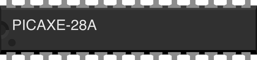
The PICAXE-28A is a versatile microcontroller designed for educational and hobbyist projects. It features 28 pins, enabling multiple input and output connections, making it ideal for controlling a variety of electronic devices. The PICAXE-28A is programmable using a simple BASIC-like language, which makes it beginner-friendly while still offering enough functionality for advanced users. It is commonly used in robotics, home automation, sensor-based systems, and other interactive electronic projects.
Explore Projects Built with PICAXE-28A
 Open Project in Cirkit Designer
 Open Project in Cirkit Designer
 Open Project in Cirkit Designer
 Open Project in Cirkit Designer
Explore Projects Built with PICAXE-28A
Open Project in Cirkit DesignerOpen Project in Cirkit DesignerOpen Project in Cirkit DesignerOpen Project in Cirkit DesignerTechnical Specifications
The PICAXE-28A microcontroller offers the following key technical details:
- Operating Voltage: 4.5V to 5.5V
- Clock Speed: 4 MHz (internal resonator)
- Programming Language: BASIC-like syntax
- Number of I/O Pins: 28 (including digital and analog pins)
- Memory: 256 bytes of EEPROM for program storage
- Communication Protocols: Serial (via programming cable)
- Power Consumption: Low power, suitable for battery-operated devices
- Package Type: DIP-28 (Dual Inline Package)
Pin Configuration and Descriptions
The PICAXE-28A has 28 pins, each with specific functions. Below is the pin configuration:
| Pin Number | Pin Name | Function |
|---|---|---|
| 1 | VSS | Ground (0V) |
| 2 | VDD | Positive power supply (4.5V to 5.5V) |
| 3 | Serial In | Serial programming input |
| 4 | Serial Out | Serial programming output |
| 5-12 | Port C (C.0-C.7) | General-purpose digital I/O pins |
| 13-20 | Port B (B.0-B.7) | General-purpose digital I/O pins (some support analog input) |
| 21-28 | Port A (A.0-A.7) | General-purpose digital I/O pins (some support PWM and analog input/output) |
Note: Some pins have dual functionality, such as supporting analog input or PWM output. Refer to the PICAXE datasheet for detailed pin-specific capabilities.
Usage Instructions
How to Use the PICAXE-28A in a Circuit
- Power Supply: Connect the VDD pin to a 5V power source and the VSS pin to ground.
- Programming: Use a PICAXE programming cable to connect the Serial In and Serial Out pins to your computer. Install the PICAXE Programming Editor software to write and upload code.
- Connecting Peripherals: Attach sensors, actuators, or other devices to the I/O pins. Ensure that the connected devices operate within the voltage and current limits of the PICAXE-28A.
- Code Upload: Write your program in the BASIC-like language supported by the PICAXE-28A. Upload the code using the programming software.
Important Considerations and Best Practices
- Power Supply: Ensure a stable 5V power supply to avoid erratic behavior.
- Pin Protection: Use resistors when connecting LEDs or other components directly to the I/O pins to prevent damage.
- Programming Cable: Use the official PICAXE programming cable for reliable communication.
- Debugging: Use the Serial Out pin to send debug messages to your computer for troubleshooting.
Example Code for Arduino-like Functionality
Below is an example of a simple program to blink an LED connected to pin B.0:
' Blink an LED connected to pin B.0
' The LED will turn on for 1 second and off for 1 second in a loop.

main:                     ' Define the main program loop
  high B.0                ' Set pin B.0 to HIGH (turn LED on)
  pause 1000              ' Wait for 1000 milliseconds (1 second)
  low B.0                 ' Set pin B.0 to LOW (turn LED off)
  pause 1000              ' Wait for 1000 milliseconds (1 second)
  goto main               ' Repeat the loop
Explanation:
high B.0: Turns on the LED by setting pin B.0 to HIGH.low B.0: Turns off the LED by setting pin B.0 to LOW.pause 1000: Introduces a delay of 1 second.
Troubleshooting and FAQs
Common Issues and Solutions
The PICAXE-28A is not responding to programming commands.
- Solution: Check the programming cable connections. Ensure the Serial In and Serial Out pins are correctly connected to the computer.
- Tip: Verify that the PICAXE Programming Editor software is installed and configured correctly.
The microcontroller behaves erratically.
- Solution: Ensure a stable 5V power supply. Check for loose connections or short circuits in the circuit.
Connected devices are not functioning as expected.
- Solution: Verify that the devices are compatible with the PICAXE-28A's voltage and current ratings. Use pull-up or pull-down resistors if required.
The LED does not blink in the example code.
- Solution: Double-check the LED polarity and ensure it is connected to pin B.0 with a suitable resistor.
FAQs
Q: Can the PICAXE-28A handle analog inputs?
A: Yes, some pins on Port B support analog input. Use thereadadccommand to read analog values.Q: What is the maximum current output per pin?
A: Each I/O pin can source or sink up to 20mA. However, the total current for all pins should not exceed 90mA.Q: Can I use the PICAXE-28A with batteries?
A: Yes, the PICAXE-28A can operate with a 4.5V to 5.5V battery pack. Ensure the voltage remains within this range.Q: Is the PICAXE-28A compatible with Arduino shields?
A: No, the PICAXE-28A is not directly compatible with Arduino shields due to differences in pin layout and programming.
This documentation provides a comprehensive guide to using the PICAXE-28A microcontroller effectively. For further details, refer to the official PICAXE datasheet and programming manual.