How to Use 1s BMS LiFePo4 12A: Examples, Pinouts, and Specs
Introduction
The 1s BMS LiFePo4 12A is a Battery Management System (BMS) designed specifically for single-series (1s) lithium iron phosphate (LiFePo4) battery packs. It is capable of handling a maximum continuous current of 12A. This component ensures the safe operation of LiFePo4 batteries by monitoring voltage levels, balancing cells, and providing protection against overcharge, over-discharge, and short circuits.
Explore Projects Built with 1s BMS LiFePo4 12A


Explore Projects Built with 1s BMS LiFePo4 12A
Common Applications and Use Cases
- Portable power banks
- Solar energy storage systems
- Electric bicycles and scooters
- Backup power supplies
- Robotics and DIY electronics projects
Technical Specifications
The following table outlines the key technical details of the 1s BMS LiFePo4 12A:
| Parameter | Value |
|---|---|
| Battery Type | LiFePo4 (Lithium Iron Phosphate) |
| Number of Cells Supported | 1 (Single Series) |
| Maximum Continuous Current | 12A |
| Overcharge Protection Voltage | 3.65V ± 0.05V |
| Over-discharge Protection Voltage | 2.0V ± 0.05V |
| Balancing Current | 30mA |
| Operating Temperature Range | -20°C to 60°C |
| Dimensions | Varies by manufacturer (e.g., 20mm x 30mm) |
| Weight | ~5g |
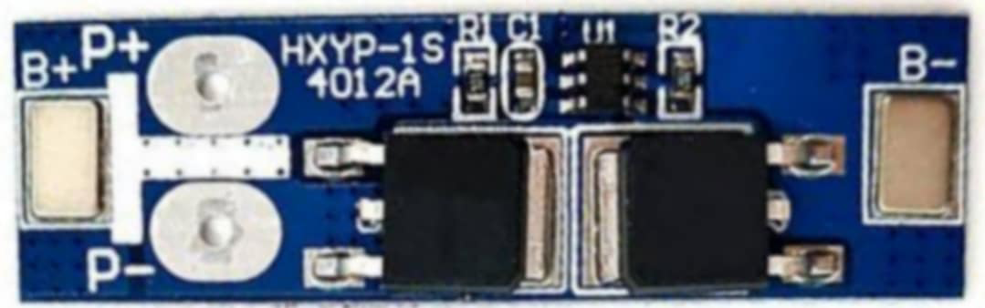
Pin Configuration and Descriptions
The 1s BMS LiFePo4 12A typically has the following pin configuration:
| Pin Name | Description |
|---|---|
| B+ | Positive terminal of the battery |
| B- | Negative terminal of the battery |
| P+ | Positive terminal of the load or charger |
| P- | Negative terminal of the load or charger |
Usage Instructions
How to Use the Component in a Circuit
Connect the Battery:
- Connect the positive terminal of the LiFePo4 battery to the
B+pin. - Connect the negative terminal of the battery to the
B-pin.
- Connect the positive terminal of the LiFePo4 battery to the
Connect the Load or Charger:
- Connect the positive terminal of the load or charger to the
P+pin. - Connect the negative terminal of the load or charger to the
P-pin.
- Connect the positive terminal of the load or charger to the
Verify Connections:
- Double-check all connections to ensure proper polarity and secure contacts.
- Ensure the battery voltage is within the supported range (2.0V to 3.65V).
Power On:
- Once all connections are secure, the BMS will automatically monitor and manage the battery.
Important Considerations and Best Practices
- Avoid Overloading: Ensure the load does not exceed the maximum continuous current of 12A.
- Use Proper Wiring: Use wires with sufficient gauge to handle the current without overheating.
- Monitor Temperature: Avoid operating the BMS in environments exceeding the specified temperature range (-20°C to 60°C).
- Balancing Cells: The BMS includes a balancing feature to equalize cell voltages. Allow sufficient time for balancing during charging.
- Charger Compatibility: Use a charger specifically designed for LiFePo4 batteries to avoid overcharging or damaging the battery.
Arduino UNO Example Code
If you are using the 1s BMS LiFePo4 12A in a project with an Arduino UNO, you can monitor the battery voltage using an analog input pin. Below is an example code snippet:
// Arduino code to monitor battery voltage using the 1s BMS LiFePo4 12A
// Connect the battery's positive terminal to an analog input pin (e.g., A0)
// Use a voltage divider if the battery voltage exceeds 5V (Arduino's ADC limit)

const int batteryPin = A0;  // Analog pin connected to the battery
const float referenceVoltage = 5.0;  // Arduino's reference voltage (5V)
const int adcResolution = 1023;  // 10-bit ADC resolution
const float voltageDividerRatio = 2.0;  // Adjust if using a voltage divider

void setup() {
  Serial.begin(9600);  // Initialize serial communication
}

void loop() {
  int adcValue = analogRead(batteryPin);  // Read the ADC value
  float batteryVoltage = (adcValue * referenceVoltage / adcResolution)
                         * voltageDividerRatio;  // Calculate battery voltage

  // Print the battery voltage to the Serial Monitor
  Serial.print("Battery Voltage: ");
  Serial.print(batteryVoltage);
  Serial.println(" V");

  delay(1000);  // Wait for 1 second before the next reading
}
Note: If the battery voltage exceeds 5V, use a voltage divider to step down the voltage to a safe level for the Arduino's analog input.
Troubleshooting and FAQs
Common Issues and Solutions
BMS Not Powering On:
- Cause: Incorrect wiring or loose connections.
- Solution: Verify all connections and ensure proper polarity.
Battery Not Charging:
- Cause: Charger not compatible with LiFePo4 batteries or insufficient voltage.
- Solution: Use a charger specifically designed for LiFePo4 batteries and ensure the charger voltage is within the supported range.
Overheating:
- Cause: Excessive current draw or poor ventilation.
- Solution: Ensure the load does not exceed 12A and provide adequate cooling.
Unbalanced Cells:
- Cause: Prolonged use without balancing or damaged cells.
- Solution: Allow the BMS to balance the cells during charging or replace damaged cells.
FAQs
Q: Can I use this BMS with other battery chemistries?
A: No, this BMS is specifically designed for LiFePo4 batteries and may not function correctly with other chemistries.
Q: What happens if the battery voltage drops below 2.0V?
A: The BMS will activate over-discharge protection and disconnect the load to prevent battery damage.
Q: Can I use this BMS for a multi-cell battery pack?
A: No, this BMS is designed for single-series (1s) battery packs only. For multi-cell packs, use a BMS designed for the appropriate configuration.
Q: How do I know if the BMS is balancing the cells?
A: The balancing process occurs automatically during charging. Some BMS modules include an LED indicator to show balancing activity.