Cirkit Designer Logo
Cirkit Designer
Your all-in-one circuit design IDE
Home / 
Component Documentation

How to Use TPS6211*: Examples, Pinouts, and Specs

Image of TPS6211*
Cirkit Designer LogoDesign with TPS6211* in Cirkit Designer

Introduction

The TPS6211* series consists of high-efficiency synchronous step-down voltage regulators designed for battery-powered and low-power applications. These integrated circuits (ICs) provide a regulated output voltage from a higher input voltage source. The series is characterized by its low quiescent current, high efficiency, and compact form factor, making it ideal for portable devices, microcontrollers, and other electronics requiring efficient power management. The asterisk (*) represents various model variants that offer different fixed output voltage options to accommodate a range of design requirements.

Explore Projects Built with TPS6211*

Use Cirkit Designer to design, explore, and prototype these projects online. Some projects support real-time simulation. Click "Open Project" to start designing instantly!
Solar-Powered Environmental Monitoring System with ESP32 and Cellular Connectivity
Image of IoT Ola: A project utilizing TPS6211* in a practical application
This circuit features an ESP32 microcontroller interfaced with a BME/BMP280 sensor for environmental data and an MH-Z19B sensor for CO2 measurement, both communicating via I2C (SCL, SDA) and serial (TX, RX) connections respectively. It includes a TP4056 module for charging an 18650 Li-ion battery from a solar panel, with a step-up boost converter to provide stable voltage to the MH-Z19B sensor and a voltage regulator for the SIM800L GSM module. The capacitors are likely used for power supply filtering or decoupling.
Cirkit Designer LogoOpen Project in Cirkit Designer
ESP32 and SIM800L-Based Smart Power Monitor with Voltage Sensors
Image of Generator state monitor: A project utilizing TPS6211* in a practical application
This circuit is a power monitoring and control system that uses an ESP32 microcontroller to read voltage and current values from multiple sensors, calculate power consumption, and send notifications via a SIM800L GSM module. It also includes a TP4056 module for battery charging, a step-up boost converter, and an AC-DC converter to power the system, with the ability to control lights through a relay based on SMS commands.
Cirkit Designer LogoOpen Project in Cirkit Designer
ESP32-Based Environmental Monitoring System with Nokia 5110 LCD and Multiple Sensors
Image of MONITORING STATION WATER QUALITY : A project utilizing TPS6211* in a practical application
This circuit is a solar-powered environmental monitoring system that uses an ESP32 microcontroller to interface with various sensors (temperature, turbidity, TDS, pH, dissolved oxygen, electrical conductivity, and ORP) and a GPS module. The system charges a 18650 Li-Ion battery via a TP4056 module connected to a solar panel, and displays data on a Nokia 5110 LCD.
Cirkit Designer LogoOpen Project in Cirkit Designer
Cellular-Enabled IoT Device with Real-Time Clock and Power Management
Image of LRCM PHASE 2 BASIC: A project utilizing TPS6211* in a practical application
This circuit features a LilyGo-SIM7000G module for cellular communication and GPS functionality, interfaced with an RTC DS3231 for real-time clock capabilities. It includes voltage sensing through two voltage sensor modules, and uses an 8-channel opto-coupler for isolating different parts of the circuit. Power management is handled by a buck converter connected to a DC power source and batteries, with a fuse for protection and a rocker switch for on/off control. Additionally, there's an LED for indication purposes.
Cirkit Designer LogoOpen Project in Cirkit Designer

Explore Projects Built with TPS6211*

Use Cirkit Designer to design, explore, and prototype these projects online. Some projects support real-time simulation. Click "Open Project" to start designing instantly!
Image of IoT Ola: A project utilizing TPS6211* in a practical application
Solar-Powered Environmental Monitoring System with ESP32 and Cellular Connectivity
This circuit features an ESP32 microcontroller interfaced with a BME/BMP280 sensor for environmental data and an MH-Z19B sensor for CO2 measurement, both communicating via I2C (SCL, SDA) and serial (TX, RX) connections respectively. It includes a TP4056 module for charging an 18650 Li-ion battery from a solar panel, with a step-up boost converter to provide stable voltage to the MH-Z19B sensor and a voltage regulator for the SIM800L GSM module. The capacitors are likely used for power supply filtering or decoupling.
Cirkit Designer LogoOpen Project in Cirkit Designer
Image of Generator state monitor: A project utilizing TPS6211* in a practical application
ESP32 and SIM800L-Based Smart Power Monitor with Voltage Sensors
This circuit is a power monitoring and control system that uses an ESP32 microcontroller to read voltage and current values from multiple sensors, calculate power consumption, and send notifications via a SIM800L GSM module. It also includes a TP4056 module for battery charging, a step-up boost converter, and an AC-DC converter to power the system, with the ability to control lights through a relay based on SMS commands.
Cirkit Designer LogoOpen Project in Cirkit Designer
Image of MONITORING STATION WATER QUALITY : A project utilizing TPS6211* in a practical application
ESP32-Based Environmental Monitoring System with Nokia 5110 LCD and Multiple Sensors
This circuit is a solar-powered environmental monitoring system that uses an ESP32 microcontroller to interface with various sensors (temperature, turbidity, TDS, pH, dissolved oxygen, electrical conductivity, and ORP) and a GPS module. The system charges a 18650 Li-Ion battery via a TP4056 module connected to a solar panel, and displays data on a Nokia 5110 LCD.
Cirkit Designer LogoOpen Project in Cirkit Designer
Image of LRCM PHASE 2 BASIC: A project utilizing TPS6211* in a practical application
Cellular-Enabled IoT Device with Real-Time Clock and Power Management
This circuit features a LilyGo-SIM7000G module for cellular communication and GPS functionality, interfaced with an RTC DS3231 for real-time clock capabilities. It includes voltage sensing through two voltage sensor modules, and uses an 8-channel opto-coupler for isolating different parts of the circuit. Power management is handled by a buck converter connected to a DC power source and batteries, with a fuse for protection and a rocker switch for on/off control. Additionally, there's an LED for indication purposes.
Cirkit Designer LogoOpen Project in Cirkit Designer

Common Applications and Use Cases

  • Portable electronic devices (e.g., smartphones, tablets)
  • Battery-powered equipment
  • Low-power microcontroller circuits
  • Energy-efficient power supplies
  • Distributed power systems

Technical Specifications

Key Technical Details

  • Input Voltage Range: 2.5V to 6V
  • Output Voltage Options: 1.2V, 1.8V, 2.5V, 3.3V, etc. (denoted by the variant number)
  • Output Current: Up to 1.5A
  • Switching Frequency: 1MHz (typical)
  • Efficiency: Up to 95%
  • Quiescent Current: 20µA (typical)
  • Operating Temperature Range: -40°C to 85°C

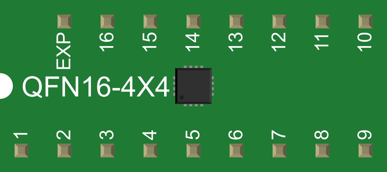
Pin Configuration and Descriptions

Pin Number Name Description
1 VIN Input voltage supply pin. Connect to the source voltage.
2 GND Ground reference for the IC.
3 SW Switch node. Connect to the inductor.
4 FB Feedback pin. Sets the output voltage through an external voltage divider.
5 EN Enable pin. A logic high enables the IC, while a logic low disables it.
6 VOS Output voltage select (for adjustable versions).
7 PG Power good output. Open-drain output that indicates when the output voltage is within regulation.

Usage Instructions

How to Use the Component in a Circuit

  1. Input Supply: Connect a suitable input voltage (2.5V to 6V) to the VIN pin.
  2. Output Voltage: For fixed output versions, the output voltage is predetermined. For adjustable versions, connect a resistor divider from the output to the FB pin to set the desired voltage.
  3. Inductor Selection: Choose an appropriate inductor value based on the desired output current and switching frequency.
  4. Capacitors: Place input and output capacitors close to the IC pins to stabilize the voltage and reduce noise.
  5. Enable Pin: Use the EN pin to turn the regulator on or off. This can be controlled by a microcontroller or a switch.

Important Considerations and Best Practices

  • Ensure that the input voltage does not exceed the maximum rating.
  • Keep the power dissipation within the IC's limits to prevent overheating.
  • Place the IC close to the power source and load to minimize trace resistance and inductance.
  • Use a solid ground plane for thermal management and noise reduction.
  • Follow the manufacturer's recommended layout guidelines for optimal performance.

Troubleshooting and FAQs

Common Issues Users Might Face

  • Output Voltage Instability: Check the input and output capacitors for proper value and placement.
  • IC Overheating: Ensure adequate thermal management and that the power dissipation is within specifications.
  • No Output Voltage: Verify that the EN pin is properly driven and that the input voltage is within the specified range.

Solutions and Tips for Troubleshooting

  • If the output voltage is incorrect, recheck the feedback resistor divider values (for adjustable versions).
  • For thermal issues, improve the PCB layout with better heat sinking or reduce the load current.
  • Ensure that the inductor and capacitors are rated for the operating frequency and current.

FAQs

Q: Can the TPS6211 be used with a microcontroller?* A: Yes, it is suitable for powering microcontrollers and other digital ICs.

Q: What is the purpose of the PG (Power Good) pin? A: The PG pin can be used to monitor the output voltage and ensure that it is within regulation before enabling other parts of the system.

Q: How do I select the correct inductor value? A: Refer to the datasheet for guidelines on inductor selection based on your specific application requirements.

Q: Can the TPS6211 series be used in parallel to increase output current?* A: No, these ICs are not designed to be used in parallel for increased current capacity.

Q: Is external compensation required? A: No, the TPS6211* series has internal compensation, simplifying the design.

Example Code for Arduino UNO

The following example demonstrates how to use the TPS6211* with an Arduino UNO to enable and disable the regulator from a digital pin.

// Define the enable pin for the TPS6211*
const int enablePin = 7; // Connect to the EN pin of the TPS6211*

void setup() {
  pinMode(enablePin, OUTPUT); // Set the enable pin as an output
}

void loop() {
  digitalWrite(enablePin, HIGH); // Enable the TPS6211*
  delay(5000); // Wait for 5 seconds
  digitalWrite(enablePin, LOW); // Disable the TPS6211*
  delay(5000); // Wait for 5 seconds
}

This code toggles the TPS6211* on and off every 5 seconds. Ensure that the enable pin is connected to the EN pin of the TPS6211* and that the output voltage is suitable for the Arduino UNO's operating voltage.