How to Use 5V Led: Examples, Pinouts, and Specs
Introduction
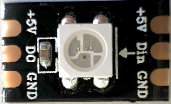
The 5V LED is a light-emitting diode (LED) designed to operate at a forward voltage of 5 volts. Unlike standard LEDs that require external current-limiting resistors, the 5V LED typically includes an internal resistor, making it easier to use in circuits. This component is widely used in electronic projects for visual indicators, status displays, and decorative lighting. Its simplicity and compatibility with common microcontrollers make it a popular choice for hobbyists and professionals alike.
Explore Projects Built with 5V Led

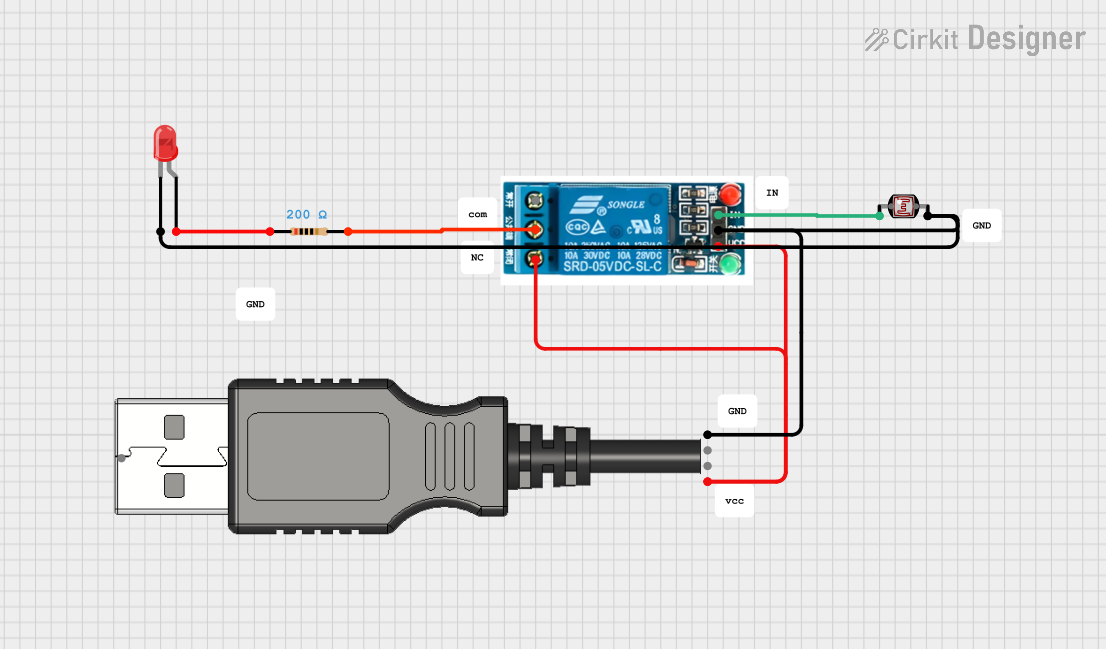
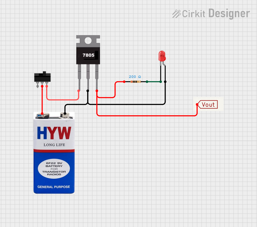

Explore Projects Built with 5V Led
Common Applications
- Power and status indicators in electronic devices
- Visual feedback in microcontroller-based projects
- Decorative lighting and displays
- Prototyping and educational projects
Technical Specifications
Below are the key technical details of the 5V LED:
| Parameter | Value |
|---|---|
| Forward Voltage (Vf) | 5V |
| Forward Current (If) | 20mA (typical) |
| Maximum Current (Imax) | 30mA |
| Wavelength (Color) | Varies (e.g., red, green, blue) |
| Viewing Angle | 20° to 30° |
| Internal Resistor | Yes |
| Operating Temperature | -40°C to +85°C |
Pin Configuration
The 5V LED has two pins:
| Pin | Name | Description |
|---|---|---|
| 1 | Anode (+) | Positive terminal; connect to the 5V power source. |
| 2 | Cathode (-) | Negative terminal; connect to ground (GND). |
Note: The longer pin is typically the anode (+), and the shorter pin is the cathode (-). If the pins are of equal length, refer to the flat edge on the LED body, which indicates the cathode.
Usage Instructions
How to Use the 5V LED in a Circuit
Direct Connection to a 5V Source:
- Connect the anode (+) of the LED to the 5V power supply.
- Connect the cathode (-) to ground (GND).
- No external resistor is required, as the LED includes an internal current-limiting resistor.
Using with a Microcontroller (e.g., Arduino UNO):
- Connect the anode (+) to a digital output pin of the microcontroller.
- Connect the cathode (-) to ground (GND).
- Use the microcontroller to control the LED state (ON/OFF) via code.
Example Code for Arduino UNO
// Example: Blink a 5V LED connected to pin 13 of the Arduino UNO

// Define the pin where the LED is connected
const int ledPin = 13;

void setup() {
  pinMode(ledPin, OUTPUT); // Set the LED pin as an output
}

void loop() {
  digitalWrite(ledPin, HIGH); // Turn the LED ON
  delay(1000);                // Wait for 1 second
  digitalWrite(ledPin, LOW);  // Turn the LED OFF
  delay(1000);                // Wait for 1 second
}
Important Considerations
- Polarity Matters: Ensure the anode (+) is connected to the positive voltage and the cathode (-) to ground. Reversing the polarity may damage the LED.
- Voltage Compatibility: Do not exceed the 5V forward voltage, as this may damage the internal resistor and the LED.
- Current Limitations: Avoid exceeding the maximum current rating (30mA) to prevent overheating or failure.
Troubleshooting and FAQs
Common Issues and Solutions
LED Does Not Light Up:
Cause: Incorrect polarity.
Solution: Verify that the anode is connected to the positive voltage and the cathode to ground.
Cause: Insufficient voltage or loose connections.
Solution: Ensure the power supply provides a stable 5V and check all connections.
LED Flickers or is Dim:
Cause: Insufficient current supply.
Solution: Ensure the power source can supply at least 20mA of current.
Cause: Faulty internal resistor.
Solution: Replace the LED with a new one.
LED Overheats or Burns Out:
- Cause: Exceeding the maximum current rating.
- Solution: Use a regulated 5V power source and avoid exceeding 30mA.
FAQs
Q: Can I use the 5V LED with a 3.3V microcontroller?
A: No, the 5V LED is designed to operate at 5V. Using it with a 3.3V microcontroller may result in insufficient brightness or failure to light up.
Q: Do I need an external resistor for the 5V LED?
A: No, the 5V LED includes an internal resistor, so no additional resistor is required.
Q: Can I connect multiple 5V LEDs in series?
A: No, connecting 5V LEDs in series will require a higher voltage than 5V. Instead, connect them in parallel, ensuring each LED receives 5V.
Q: How do I identify the anode and cathode if the pins are the same length?
A: Look for the flat edge on the LED body, which indicates the cathode (-). The opposite side is the anode (+).