Cirkit Designer Logo
Cirkit Designer
Your all-in-one circuit design IDE
Home / 
Component Documentation

How to Use Smart Elex RLS-08 Anolog and Digital Line Follower Sensor: Examples, Pinouts, and Specs

Image of Smart Elex RLS-08 Anolog and Digital Line Follower Sensor
Cirkit Designer LogoDesign with Smart Elex RLS-08 Anolog and Digital Line Follower Sensor in Cirkit Designer

Introduction

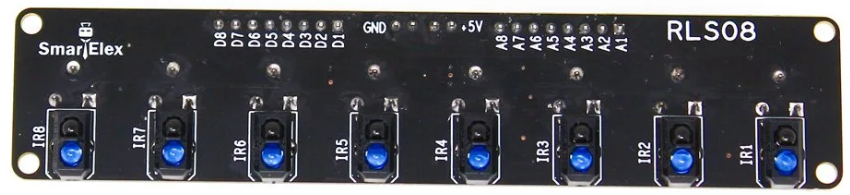
The Smart Elex RLS-08 Analog and Digital Line Follower Sensor is a versatile sensor designed to detect lines on the ground. It provides both analog and digital outputs, making it suitable for a wide range of applications. This sensor is commonly used in robotics, particularly in line-following robots, where it helps the robot detect and follow a predefined path. Its compact design and dual output functionality make it an excellent choice for hobbyists and professionals alike.

Explore Projects Built with Smart Elex RLS-08 Anolog and Digital Line Follower Sensor

Use Cirkit Designer to design, explore, and prototype these projects online. Some projects support real-time simulation. Click "Open Project" to start designing instantly!
Arduino-Controlled Line-Following Robot with Ultrasonic Obstacle Detection
Image of RAD project: A project utilizing Smart Elex RLS-08 Anolog and Digital Line Follower Sensor in a practical application
This circuit is designed for a line-following and obstacle-avoiding robot. It uses an Arduino UNO to control two DC motors via an L298N motor driver, based on input from IR sensors for line detection and an HC-SR04 ultrasonic sensor for distance measurement. The Arduino's firmware is programmed to adjust the robot's path in response to detected lines and obstacles, ensuring it follows a predetermined path while avoiding collisions.
Cirkit Designer LogoOpen Project in Cirkit Designer
Arduino Leonardo-Based Line Following Robot with TCRT-5000 IR Sensors and L298N Motor Driver
Image of compt_neapolis_nebeul: A project utilizing Smart Elex RLS-08 Anolog and Digital Line Follower Sensor in a practical application
This circuit is a line-following robot that uses four TCRT-5000 IR sensors to detect the path and an Arduino Leonardo to process the sensor data. The Arduino controls two DC motors via an L298N motor driver module, powered by a 7.4V battery and a rocker switch for power control.
Cirkit Designer LogoOpen Project in Cirkit Designer
Arduino UNO Controlled Robotics System with RFID and Ultrasonic Sensing
Image of UTS ULTRASONIK: A project utilizing Smart Elex RLS-08 Anolog and Digital Line Follower Sensor in a practical application
This is a multi-sensor system with actuation and display capabilities, featuring an Arduino UNO that controls ultrasonic sensors for distance measurement, servos for movement, RFID modules for identification tasks, and an LCD for output display. The system is designed for interactive applications that require environmental sensing, object manipulation, and user feedback.
Cirkit Designer LogoOpen Project in Cirkit Designer
Arduino UNO-Based Smart Sensor Hub with RFID and Load Cell Integration
Image of khoa học kỹ thuậtttt: A project utilizing Smart Elex RLS-08 Anolog and Digital Line Follower Sensor in a practical application
This circuit is a multi-sensor system controlled by an Arduino UNO, integrating various sensors and modules such as an RFID reader, MPU6050 accelerometer, load cell with HX711 interface, DHT11 temperature and humidity sensor, water level sensor, IR receiver, RGB LED, buzzer, and an I2C LCD screen. The system is designed to collect and display environmental data, detect RFID tags, measure weight, and provide visual and auditory feedback.
Cirkit Designer LogoOpen Project in Cirkit Designer

Explore Projects Built with Smart Elex RLS-08 Anolog and Digital Line Follower Sensor

Use Cirkit Designer to design, explore, and prototype these projects online. Some projects support real-time simulation. Click "Open Project" to start designing instantly!
Image of RAD project: A project utilizing Smart Elex RLS-08 Anolog and Digital Line Follower Sensor in a practical application
Arduino-Controlled Line-Following Robot with Ultrasonic Obstacle Detection
This circuit is designed for a line-following and obstacle-avoiding robot. It uses an Arduino UNO to control two DC motors via an L298N motor driver, based on input from IR sensors for line detection and an HC-SR04 ultrasonic sensor for distance measurement. The Arduino's firmware is programmed to adjust the robot's path in response to detected lines and obstacles, ensuring it follows a predetermined path while avoiding collisions.
Cirkit Designer LogoOpen Project in Cirkit Designer
Image of compt_neapolis_nebeul: A project utilizing Smart Elex RLS-08 Anolog and Digital Line Follower Sensor in a practical application
Arduino Leonardo-Based Line Following Robot with TCRT-5000 IR Sensors and L298N Motor Driver
This circuit is a line-following robot that uses four TCRT-5000 IR sensors to detect the path and an Arduino Leonardo to process the sensor data. The Arduino controls two DC motors via an L298N motor driver module, powered by a 7.4V battery and a rocker switch for power control.
Cirkit Designer LogoOpen Project in Cirkit Designer
Image of UTS ULTRASONIK: A project utilizing Smart Elex RLS-08 Anolog and Digital Line Follower Sensor in a practical application
Arduino UNO Controlled Robotics System with RFID and Ultrasonic Sensing
This is a multi-sensor system with actuation and display capabilities, featuring an Arduino UNO that controls ultrasonic sensors for distance measurement, servos for movement, RFID modules for identification tasks, and an LCD for output display. The system is designed for interactive applications that require environmental sensing, object manipulation, and user feedback.
Cirkit Designer LogoOpen Project in Cirkit Designer
Image of khoa học kỹ thuậtttt: A project utilizing Smart Elex RLS-08 Anolog and Digital Line Follower Sensor in a practical application
Arduino UNO-Based Smart Sensor Hub with RFID and Load Cell Integration
This circuit is a multi-sensor system controlled by an Arduino UNO, integrating various sensors and modules such as an RFID reader, MPU6050 accelerometer, load cell with HX711 interface, DHT11 temperature and humidity sensor, water level sensor, IR receiver, RGB LED, buzzer, and an I2C LCD screen. The system is designed to collect and display environmental data, detect RFID tags, measure weight, and provide visual and auditory feedback.
Cirkit Designer LogoOpen Project in Cirkit Designer

Common Applications

  • Line-following robots
  • Path detection in automated guided vehicles (AGVs)
  • Obstacle avoidance systems
  • Edge detection in conveyor belts
  • Educational robotics projects

Technical Specifications

Below are the key technical details of the Smart Elex RLS-08 sensor:

Parameter Value
Manufacturer Smart Elex
Part ID Line Follower Sensor
Operating Voltage 3.3V to 5V
Output Type Analog and Digital
Detection Range 1mm to 12mm (optimal: 3mm to 5mm)
Sensor Type Infrared (IR)
Dimensions 32mm x 14mm x 7mm
Mounting Holes 2 x M3
Weight 5g

Pin Configuration and Descriptions

The sensor has a 3-pin interface for easy integration into circuits. Below is the pinout:

Pin Name Description
1 VCC Power supply input (3.3V to 5V). Connect to the positive terminal of the power.
2 GND Ground. Connect to the negative terminal of the power supply.
3 OUT Output signal. Provides both analog and digital signals based on line detection.

Usage Instructions

How to Use the Sensor in a Circuit

  1. Power the Sensor: Connect the VCC pin to a 3.3V or 5V power source and the GND pin to the ground.
  2. Connect the Output: Use the OUT pin to read the sensor's output. The output can be connected to a microcontroller (e.g., Arduino) or directly to an LED for testing.
    • Digital Output: The sensor outputs a HIGH signal (logic 1) when it detects a white surface and a LOW signal (logic 0) when it detects a black surface.
    • Analog Output: The sensor provides a variable voltage proportional to the intensity of the reflected light.
  3. Adjust the Sensitivity: Use the onboard potentiometer to fine-tune the sensor's sensitivity for optimal performance.

Important Considerations and Best Practices

  • Optimal Distance: Ensure the sensor is placed 3mm to 5mm above the surface for accurate detection.
  • Surface Contrast: Use surfaces with high contrast (e.g., black lines on a white background) for best results.
  • Ambient Light: Avoid using the sensor in environments with excessive ambient light, as it may interfere with the IR detection.
  • Wiring: Keep the wiring short to minimize noise and interference.

Example Code for Arduino UNO

Below is an example code snippet to use the RLS-08 sensor with an Arduino UNO:

// Define the sensor output pin
const int sensorPin = 2; // Connect the OUT pin of the sensor to digital pin 2

void setup() {
  pinMode(sensorPin, INPUT); // Set the sensor pin as input
  Serial.begin(9600);        // Initialize serial communication at 9600 baud
}

void loop() {
  int sensorValue = digitalRead(sensorPin); // Read the digital output of the sensor

  if (sensorValue == HIGH) {
    // If the sensor detects a white surface
    Serial.println("White surface detected");
  } else {
    // If the sensor detects a black surface
    Serial.println("Black surface detected");
  }

  delay(100); // Add a small delay for stability
}

Notes:

  • If you want to use the analog output, connect the OUT pin to an analog input pin on the Arduino (e.g., A0) and use analogRead() instead of digitalRead().

Troubleshooting and FAQs

Common Issues and Solutions

  1. Sensor Not Detecting Lines

    • Cause: Incorrect placement or distance from the surface.
    • Solution: Adjust the sensor height to 3mm-5mm above the surface and ensure the surface has high contrast.
  2. Inconsistent Readings

    • Cause: Ambient light interference or improper sensitivity settings.
    • Solution: Reduce ambient light or adjust the potentiometer to fine-tune the sensitivity.
  3. No Output Signal

    • Cause: Incorrect wiring or insufficient power supply.
    • Solution: Double-check the wiring and ensure the power supply is within the specified range (3.3V to 5V).
  4. Output Always HIGH or LOW

    • Cause: Faulty sensor or improper surface contrast.
    • Solution: Test the sensor on a known high-contrast surface. If the issue persists, consider replacing the sensor.

FAQs

Q1: Can I use this sensor with a 3.3V microcontroller?
A1: Yes, the sensor operates within a voltage range of 3.3V to 5V, making it compatible with 3.3V microcontrollers.

Q2: How do I know if the sensor is working?
A2: You can test the sensor by connecting an LED to the OUT pin. The LED should turn ON when a white surface is detected and OFF when a black surface is detected.

Q3: Can I use multiple sensors for a robot?
A3: Yes, you can use multiple RLS-08 sensors to create a more robust line-following system. Connect each sensor to a separate input pin on your microcontroller.

Q4: What is the difference between analog and digital output?
A4: The digital output provides a binary signal (HIGH or LOW) based on line detection, while the analog output provides a variable voltage proportional to the intensity of the reflected light.

By following this documentation, you can effectively integrate and use the Smart Elex RLS-08 Analog and Digital Line Follower Sensor in your projects.