Cirkit Designer Logo
Cirkit Designer
Your all-in-one circuit design IDE
Home / 
Component Documentation

How to Use Adafruit 16x8 LED Matrix Backpack White: Examples, Pinouts, and Specs

Image of Adafruit 16x8 LED Matrix Backpack White
Cirkit Designer LogoDesign with Adafruit 16x8 LED Matrix Backpack White in Cirkit Designer

Introduction

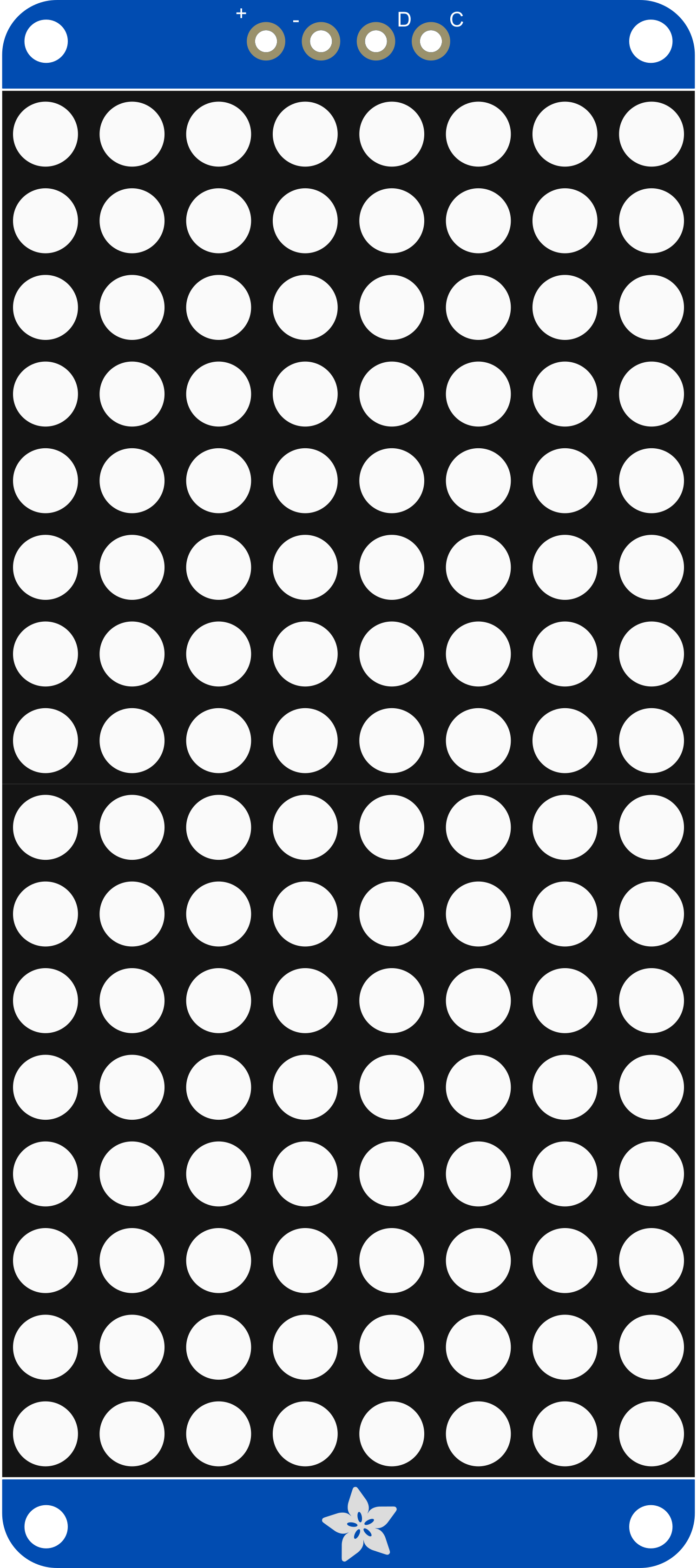
The Adafruit 16x8 LED Matrix Backpack White is a versatile and compact LED matrix display module that provides a resolution of 16x8, meaning it has 16 columns and 8 rows of white LEDs. This component is ideal for displaying monochrome graphics, text, and simple animations. It is commonly used in wearables, status indicators, and small message displays. The included backpack module simplifies the connection to microcontrollers, such as the Arduino UNO, by using the I2C interface, which minimizes the number of pins required for operation.

Explore Projects Built with Adafruit 16x8 LED Matrix Backpack White

Use Cirkit Designer to design, explore, and prototype these projects online. Some projects support real-time simulation. Click "Open Project" to start designing instantly!
Arduino-Controlled RGB LED Matrix Display
Image of SMD2121 Led screen: A project utilizing Adafruit 16x8 LED Matrix Backpack White in a practical application
This circuit connects an Arduino UNO R4 WiFi microcontroller to a 64x32 LED matrix display. The Arduino is configured to control the LED matrix, sending color data and control signals to display various colors across the matrix. The embedded code on the Arduino cycles through a range of colors, filling the entire LED matrix with each color in sequence.
Cirkit Designer LogoOpen Project in Cirkit Designer
Arduino UNO WiFi-Controlled LED Matrix Display
Image of SMD2121 Led screen - r4: A project utilizing Adafruit 16x8 LED Matrix Backpack White in a practical application
This circuit consists of an Arduino UNO R4 WiFi microcontroller connected to a 64x32 LED matrix. The Arduino controls the LED matrix by sending signals to various pins to display different colors and patterns, as defined in the embedded code.
Cirkit Designer LogoOpen Project in Cirkit Designer
ESP32-Controlled Dual 8x8 LED Matrix Display with NTP Time Synchronization
Image of time: A project utilizing Adafruit 16x8 LED Matrix Backpack White in a practical application
This circuit features an ESP32 microcontroller connected to two cascaded 8x8 LED matrix displays, powered by a 3.3V battery. The ESP32 drives the displays to show time and other information, with the code indicating functionality for connecting to WiFi, synchronizing time via NTP, and displaying data on the matrices using custom fonts. Additionally, there is a separate 3.3V battery powering a red LED, which appears to function as a simple indicator light.
Cirkit Designer LogoOpen Project in Cirkit Designer
Arduino UNO Controlled RGB LED Matrix with Bluetooth Connectivity and Audio Output
Image of the bell : A project utilizing Adafruit 16x8 LED Matrix Backpack White in a practical application
This is an interactive display and communication circuit. It uses an Arduino UNO to drive multiple WS2812 RGB LED matrices for visual output, interfaces with a DS3231 RTC for time-related functions, and communicates wirelessly via an HC-05 Bluetooth module. Additionally, it features audio output capabilities through a speaker connected to a PAM8403 audio amplifier.
Cirkit Designer LogoOpen Project in Cirkit Designer

Explore Projects Built with Adafruit 16x8 LED Matrix Backpack White

Use Cirkit Designer to design, explore, and prototype these projects online. Some projects support real-time simulation. Click "Open Project" to start designing instantly!
Image of SMD2121 Led screen: A project utilizing Adafruit 16x8 LED Matrix Backpack White in a practical application
Arduino-Controlled RGB LED Matrix Display
This circuit connects an Arduino UNO R4 WiFi microcontroller to a 64x32 LED matrix display. The Arduino is configured to control the LED matrix, sending color data and control signals to display various colors across the matrix. The embedded code on the Arduino cycles through a range of colors, filling the entire LED matrix with each color in sequence.
Cirkit Designer LogoOpen Project in Cirkit Designer
Image of SMD2121 Led screen - r4: A project utilizing Adafruit 16x8 LED Matrix Backpack White in a practical application
Arduino UNO WiFi-Controlled LED Matrix Display
This circuit consists of an Arduino UNO R4 WiFi microcontroller connected to a 64x32 LED matrix. The Arduino controls the LED matrix by sending signals to various pins to display different colors and patterns, as defined in the embedded code.
Cirkit Designer LogoOpen Project in Cirkit Designer
Image of time: A project utilizing Adafruit 16x8 LED Matrix Backpack White in a practical application
ESP32-Controlled Dual 8x8 LED Matrix Display with NTP Time Synchronization
This circuit features an ESP32 microcontroller connected to two cascaded 8x8 LED matrix displays, powered by a 3.3V battery. The ESP32 drives the displays to show time and other information, with the code indicating functionality for connecting to WiFi, synchronizing time via NTP, and displaying data on the matrices using custom fonts. Additionally, there is a separate 3.3V battery powering a red LED, which appears to function as a simple indicator light.
Cirkit Designer LogoOpen Project in Cirkit Designer
Image of the bell : A project utilizing Adafruit 16x8 LED Matrix Backpack White in a practical application
Arduino UNO Controlled RGB LED Matrix with Bluetooth Connectivity and Audio Output
This is an interactive display and communication circuit. It uses an Arduino UNO to drive multiple WS2812 RGB LED matrices for visual output, interfaces with a DS3231 RTC for time-related functions, and communicates wirelessly via an HC-05 Bluetooth module. Additionally, it features audio output capabilities through a speaker connected to a PAM8403 audio amplifier.
Cirkit Designer LogoOpen Project in Cirkit Designer

Technical Specifications

Key Technical Details

  • Resolution: 16x8 (128 LEDs)
  • LED Color: White
  • Communication Interface: I2C
  • Operating Voltage: 5V DC
  • Maximum Current: 500mA (all LEDs on)
  • Dimensions: 1.2" x 2.7" (approximate)

Pin Configuration and Descriptions

Pin Description
GND Ground connection
VCC Power supply (5V input)
SDA I2C data line
SCL I2C clock line
ADDR I2C address selection (connect to GND or VCC)

Usage Instructions

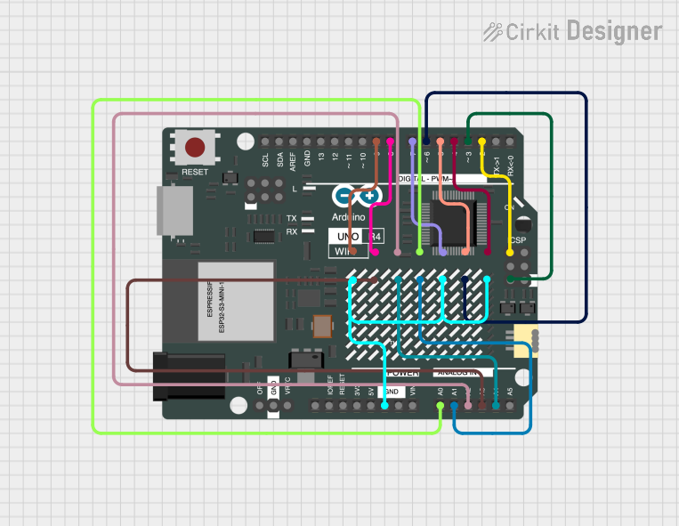
Connecting to a Circuit

  1. Connect the GND pin to the ground of your microcontroller.
  2. Connect the VCC pin to a 5V supply from your microcontroller.
  3. Connect the SDA and SCL pins to the corresponding I2C data and clock lines on your microcontroller.
  4. Optionally, connect the ADDR pin to GND or VCC to set the I2C address if using multiple displays.

Important Considerations and Best Practices

  • Ensure that your power supply can handle the maximum current draw if all LEDs are lit.
  • Use pull-up resistors on the SDA and SCL lines if they are not built into your microcontroller.
  • Avoid looking directly at the LEDs when they are powered to prevent eye strain or damage.
  • When programming, take advantage of the Adafruit LED Backpack library to simplify code development.

Example Code for Arduino UNO

#include <Wire.h>
#include <Adafruit_GFX.h>
#include <Adafruit_LEDBackpack.h>

Adafruit_8x16matrix matrix = Adafruit_8x16matrix();

void setup() {
  matrix.begin(0x70); // Initialize the display with its I2C address
  matrix.setBrightness(10); // Set brightness to a medium level
}

void loop() {
  matrix.clear(); // Clear the display buffer
  matrix.setCursor(0, 0); // Set cursor at top-left corner
  matrix.print("Hello"); // Print "Hello" on the display
  matrix.writeDisplay(); // Update the display with the buffer content
  delay(2000); // Wait for 2 seconds
}

Ensure that the Adafruit GFX and LED Backpack libraries are installed in your Arduino IDE before uploading this code to your Arduino UNO.

Troubleshooting and FAQs

Common Issues

  • Display not lighting up: Check the power connections and ensure the I2C address is correct.
  • Dim or flickering LEDs: Verify that the power supply is stable and can provide sufficient current.
  • Garbled text or graphics: Ensure that the SDA and SCL connections are secure and that there are pull-up resistors if needed.

Solutions and Tips for Troubleshooting

  • Double-check wiring, especially the I2C lines and power connections.
  • Use the i2cdetect utility or similar tools to confirm the device's I2C address.
  • Make sure the Adafruit libraries are up-to-date and correctly included in your Arduino sketch.

FAQs

Q: Can I daisy-chain multiple LED matrix backpacks? A: Yes, you can connect multiple backpacks in series by connecting the SDA and SCL lines together and providing separate power if needed. Remember to set unique I2C addresses for each backpack.

Q: How do I change the brightness of the display? A: Use the setBrightness() function in your code to adjust the brightness level from 0 (off) to 15 (maximum brightness).

Q: What is the maximum number of characters that can be displayed? A: The number of characters depends on the font size. With the default 5x7 font, you can display up to two characters at a time.

For further assistance, consult the Adafruit support forums or the detailed product guide available on the Adafruit website.