How to Use Adafruit LTC4311 I2C Extender: Examples, Pinouts, and Specs
Introduction
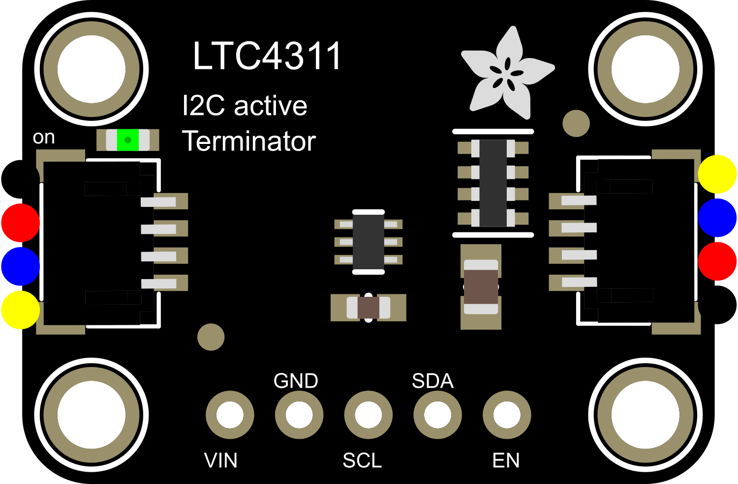
The Adafruit LTC4311 I2C Extender is an electronic component designed to enhance the capabilities of the I2C communication bus. It serves as an active I2C repeater, enabling longer distances between I2C devices without signal degradation. This extender is particularly useful in applications where I2C devices are spread out or where signal integrity is compromised due to long cable lengths. It supports standard I2C bus speeds and offers level shifting, making it compatible with both 3.3V and 5V systems.
Common applications include:
- Extending I2C communication in large-scale projects.
- Improving signal integrity in noisy environments.
- Bridging I2C devices operating at different voltage levels.
Explore Projects Built with Adafruit LTC4311 I2C Extender

Explore Projects Built with Adafruit LTC4311 I2C Extender
Technical Specifications
Key Technical Details
- Supply Voltage (VCC): 2.5V to 5.5V
- Logic Levels: Compatible with 3.3V and 5V systems
- Maximum Continuous Current: 10mA
- Operating Temperature Range: -40°C to 85°C
- I2C Bus Speed: Supports standard mode (100kHz) and fast mode (400kHz)
Pin Configuration and Descriptions
| Pin Number | Pin Name | Description |
|---|---|---|
| 1 | VCC | Power supply (2.5V to 5.5V) |
| 2 | GND | Ground |
| 3 | SDA1 | I2C Data Line for upstream connection |
| 4 | SCL1 | I2C Clock Line for upstream connection |
| 5 | SDA2 | I2C Data Line for downstream connection |
| 6 | SCL2 | I2C Clock Line for downstream connection |
Usage Instructions
How to Use the Component in a Circuit
Power Connections: Connect the VCC pin to your power supply (2.5V to 5.5V) and the GND pin to the ground.
I2C Connections: Connect the SDA1 and SCL1 pins to the I2C data and clock lines of your microcontroller (e.g., Arduino). Connect the SDA2 and SCL2 pins to the I2C data and clock lines of the I2C device or bus you wish to extend.
Level Shifting: If you are connecting devices that operate at different logic levels, the LTC4311 will automatically shift the levels appropriately.
Important Considerations and Best Practices
- Ensure that pull-up resistors are installed on the I2C lines if they are not already present in your setup.
- Keep the I2C cable lengths as short as possible to minimize potential signal degradation.
- Avoid running I2C lines near high-voltage or high-current traces to prevent interference.
- Use twisted pair cables for SDA and SCL lines to improve noise immunity.
Troubleshooting and FAQs
Common Issues
- Signal Degradation: If you notice unreliable communication, check the integrity of your I2C lines and the distance between devices.
- Mismatched Logic Levels: Ensure that all devices on the I2C bus can operate at the logic level provided.
Solutions and Tips
- Signal Integrity: Use shielded cables and consider adding ferrite beads to reduce noise.
- Logic Level Compatibility: Verify that all devices are compatible with the logic levels being used. If necessary, use additional level shifters.
FAQs
Q: What is the maximum distance the LTC4311 can extend an I2C bus? A: The maximum distance depends on various factors such as bus speed, cable quality, and environmental conditions. In general, the LTC4311 can extend I2C communication up to a few meters.
Q: Can the LTC4311 be used with high-speed I2C modes? A: The LTC4311 is designed for standard (100kHz) and fast mode (400kHz) I2C communications. It does not support high-speed mode (3.4MHz).
Q: Do I need external pull-up resistors for the SDA and SCL lines? A: Yes, pull-up resistors are typically required for I2C lines. The LTC4311 does not have built-in pull-up resistors.
Example Arduino Code
Below is an example of how to use the Adafruit LTC4311 I2C Extender with an Arduino UNO. This example assumes you are connecting an I2C sensor that is compatible with the Arduino Wire library.
#include <Wire.h>

void setup() {
  Wire.begin(); // Initialize I2C communication
  Serial.begin(9600); // Start serial communication for debugging

  // Configure sensor (if necessary)
  // Wire.beginTransmission(SENSOR_ADDRESS);
  // Wire.write(CONFIGURATION_COMMANDS);
  // Wire.endTransmission();
}

void loop() {
  // Request data from the sensor
  Wire.requestFrom(SENSOR_ADDRESS, NUMBER_OF_BYTES);
  while (Wire.available()) {
    char c = Wire.read(); // receive a byte as character
    Serial.print(c); // print the character
  }

  delay(1000); // Wait for 1 second before next request
}
Remember to replace SENSOR_ADDRESS and NUMBER_OF_BYTES with the appropriate values for your specific I2C device. If your sensor requires specific configuration commands, include them in the setup() function.
Note: This code is for illustration purposes only and may require modifications to work with your specific I2C device.