
How to Use 2x12 terminal block: Examples, Pinouts, and Specs

 Design with 2x12 terminal block in Cirkit Designer
Introduction
A 2x12 terminal block is a type of electrical connector designed to facilitate the connection of multiple wires in a compact and organized manner. It features two rows of 12 terminals, providing a total of 24 connection points. This component is widely used in electrical and electronic systems to simplify wiring, ensure secure connections, and allow for easy maintenance or modifications.
Explore Projects Built with 2x12 terminal block
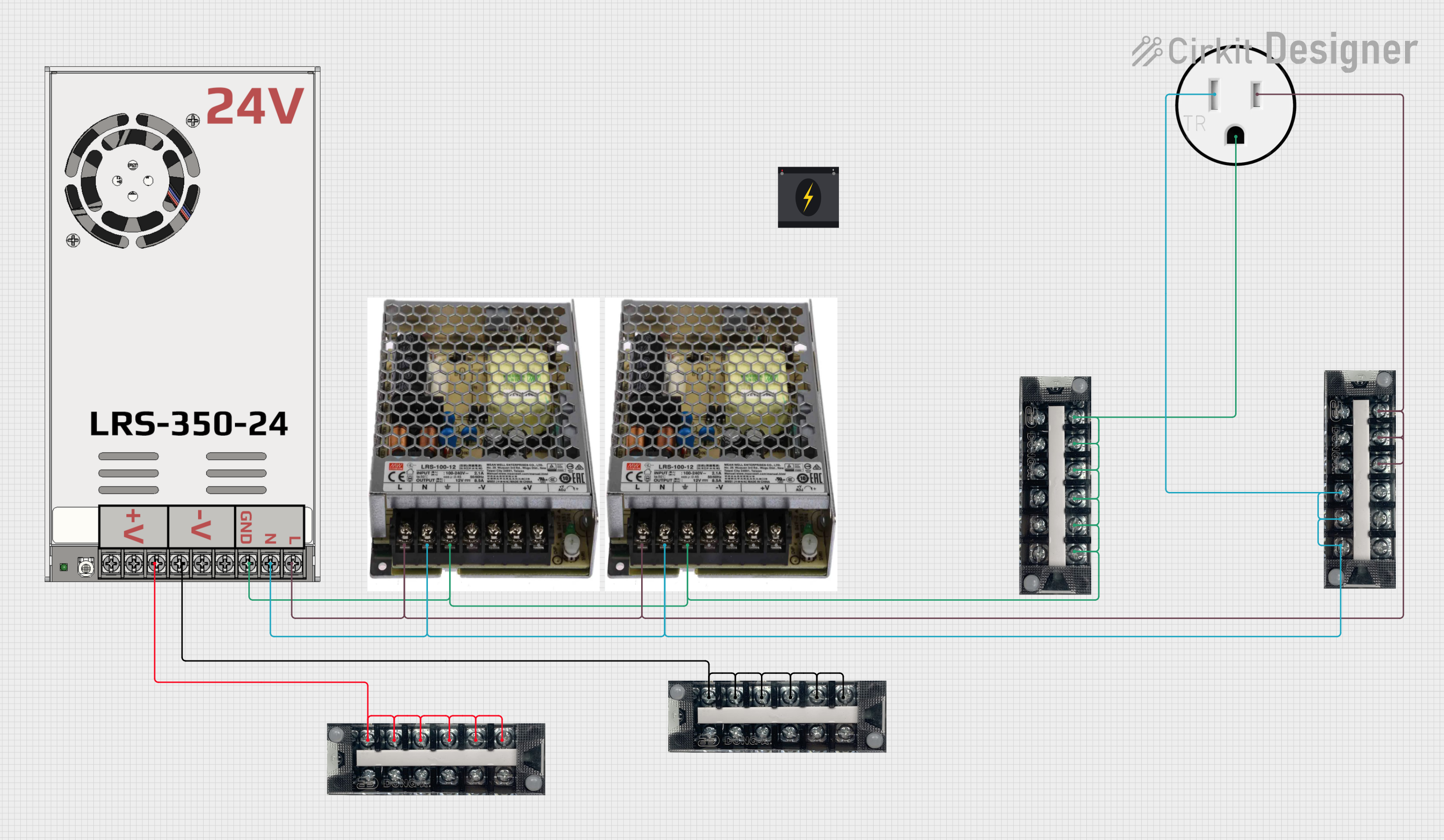 Open Project in Cirkit Designer
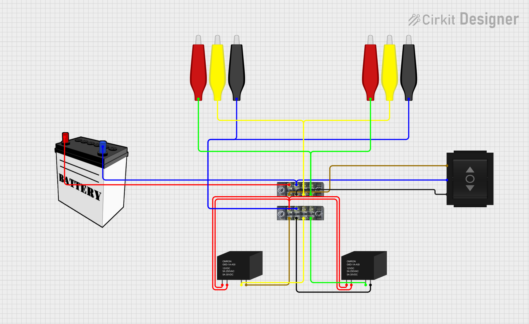 Open Project in Cirkit Designer
 Open Project in Cirkit Designer
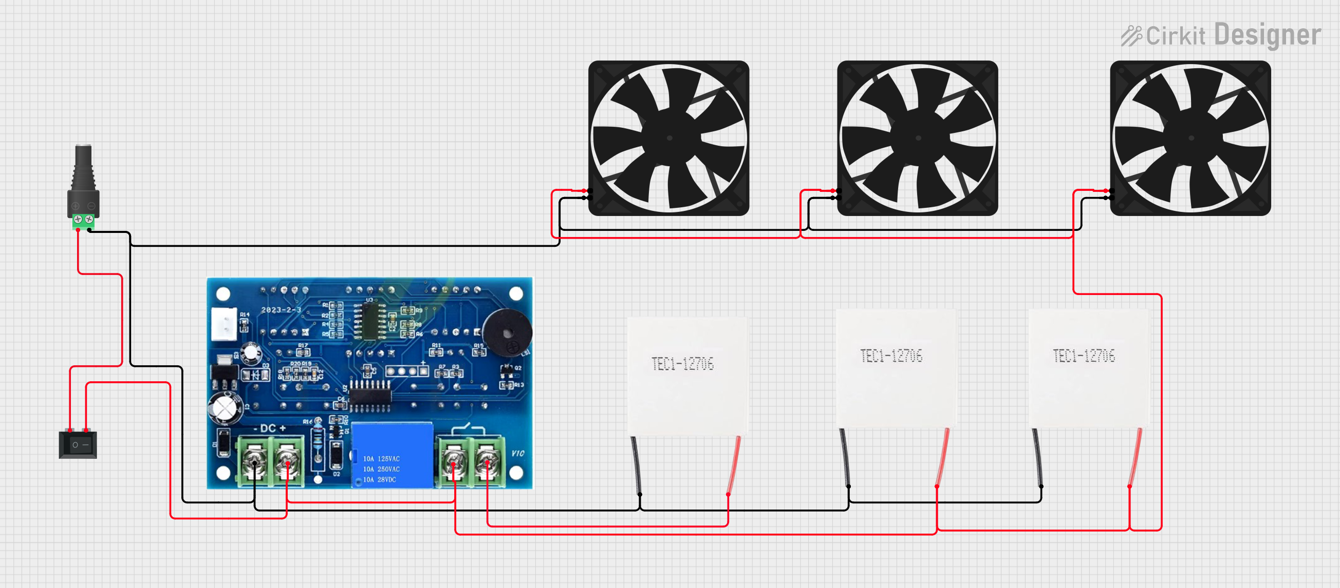 Open Project in Cirkit Designer
Explore Projects Built with 2x12 terminal block
Open Project in Cirkit DesignerOpen Project in Cirkit DesignerOpen Project in Cirkit DesignerOpen Project in Cirkit DesignerCommon Applications and Use Cases
- Industrial control panels and automation systems
- Power distribution in electrical circuits
- Prototyping and testing of electronic circuits
- Audio and signal distribution systems
- Home and building electrical wiring projects
Technical Specifications
The following table outlines the key technical details of a standard 2x12 terminal block:
| Parameter | Specification |
|---|---|
| Number of Terminals | 24 (2 rows of 12 terminals) |
| Terminal Pitch | 5.08 mm (standard spacing) |
| Rated Voltage | Up to 300V |
| Rated Current | Up to 15A |
| Wire Gauge Compatibility | 12–24 AWG |
| Material (Body) | Polyamide (flame-retardant) |
| Material (Contacts) | Brass with nickel or tin plating |
| Mounting Type | Screw-down or PCB mountable |
| Operating Temperature | -40°C to +105°C |
Pin Configuration and Descriptions
The 2x12 terminal block does not have traditional "pins" like an IC but instead features screw terminals for wire connections. Below is a description of its layout:
| Row | Terminal Numbers | Description |
|---|---|---|
| Top | 1–12 | Positive or signal connections |
| Bottom | 13–24 | Negative, ground, or signal return |
Each terminal is paired vertically (e.g., Terminal 1 aligns with Terminal 13, Terminal 2 aligns with Terminal 14, etc.), allowing for easy pairing of signal and ground wires.
Usage Instructions
How to Use the 2x12 Terminal Block in a Circuit
- Prepare the Wires: Strip the insulation from the ends of the wires you intend to connect. Ensure the exposed wire length matches the terminal block's specifications (typically 5–7 mm).
- Insert the Wires: Loosen the screw on the desired terminal, insert the stripped wire into the opening, and tighten the screw to secure the connection. Avoid overtightening to prevent damage to the wire or terminal.
- Connect to the Circuit: Use the terminal block to connect wires from different components, such as power supplies, sensors, or actuators, ensuring proper polarity and signal routing.
- Mount the Terminal Block: Secure the terminal block to a PCB, DIN rail, or enclosure as required by your application.
Important Considerations and Best Practices
- Wire Gauge: Ensure the wires used are within the terminal block's supported range (12–24 AWG).
- Tight Connections: Check that all screws are securely tightened to avoid loose connections, which can lead to electrical faults.
- Polarity: Clearly label the terminals to avoid wiring errors, especially in power distribution applications.
- Insulation: Use insulated ferrules for stranded wires to improve connection reliability and prevent fraying.
- Spacing: Maintain adequate spacing between adjacent terminal blocks to prevent short circuits.
Example: Connecting to an Arduino UNO
The 2x12 terminal block can be used to organize connections between an Arduino UNO and external components. Below is an example of wiring an LED and a button using the terminal block:
Circuit Description
- Terminal 1: Connected to Arduino's digital pin 8 (LED positive).
- Terminal 13: Connected to Arduino's GND (LED negative).
- Terminal 2: Connected to Arduino's digital pin 7 (button input).
- Terminal 14: Connected to Arduino's GND (button ground).
Arduino Code Example
// Define pin connections
const int ledPin = 8;  // LED connected to terminal 1
const int buttonPin = 7;  // Button connected to terminal 2

void setup() {
  pinMode(ledPin, OUTPUT);  // Set LED pin as output
  pinMode(buttonPin, INPUT_PULLUP);  // Set button pin as input with pull-up
}

void loop() {
  // Read the button state
  int buttonState = digitalRead(buttonPin);

  // Turn LED on if button is pressed, off otherwise
  if (buttonState == LOW) {  // Button pressed (LOW due to pull-up resistor)
    digitalWrite(ledPin, HIGH);  // Turn LED on
  } else {
    digitalWrite(ledPin, LOW);  // Turn LED off
  }
}
Troubleshooting and FAQs
Common Issues and Solutions
Loose Connections
- Issue: Wires are not securely held in the terminal block.
- Solution: Ensure screws are tightened properly. Use ferrules for stranded wires.
Overheating
- Issue: Terminal block becomes hot during operation.
- Solution: Check that the current does not exceed the rated 15A. Use thicker wires if necessary.
Short Circuits
- Issue: Adjacent terminals are shorted.
- Solution: Verify proper wire insulation and maintain spacing between terminal blocks.
Wire Fraying
- Issue: Stranded wires fray when inserted into the terminal.
- Solution: Use insulated ferrules or tin the wire ends with solder.
FAQs
Q: Can I use the 2x12 terminal block for high-frequency signals?
A: Yes, but ensure the signal integrity is maintained by minimizing wire length and avoiding interference.
Q: Is the terminal block suitable for outdoor use?
A: Standard terminal blocks are not weatherproof. Use an enclosure or select a weatherproof model for outdoor applications.
Q: Can I connect multiple wires to a single terminal?
A: It is not recommended as it may compromise the connection quality. Use a larger terminal block or a bus bar for such applications.