
Cirkit Designer
Your all-in-one circuit design IDE
Home /
Component Documentation
How to Use SC16IS752: Examples, Pinouts, and Specs
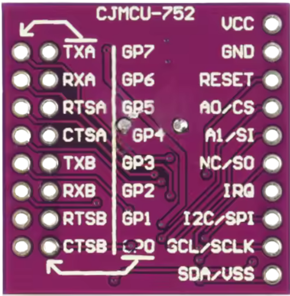
 Design with SC16IS752 in Cirkit Designer
Introduction
The SC16IS752, manufactured by NXP, is a dual-channel I2C/SPI to UART bridge designed to facilitate serial communication between microcontrollers and other devices. It provides a high-speed UART interface with configurable baud rates and supports both I2C and SPI protocols, making it a versatile solution for embedded systems. This component is particularly useful in applications requiring multiple UART interfaces but limited microcontroller resources.
Explore Projects Built with SC16IS752
STM32F103C8T6-Based Spectral Sensor with ST7735S Display and Pushbutton Control
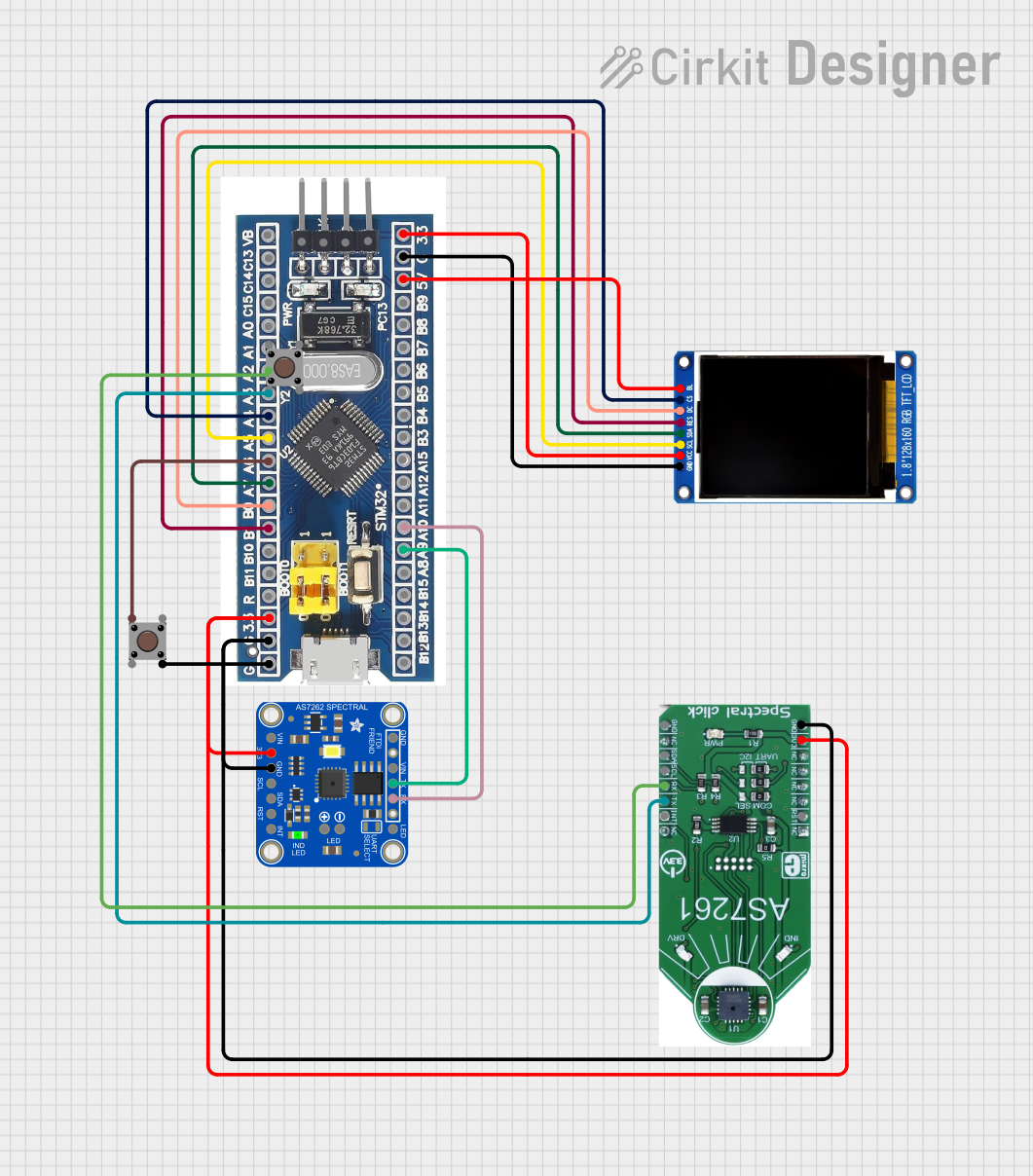
This circuit features an STM32F103C8T6 microcontroller interfaced with a China ST7735S 160x128 display and two spectral sensors (Adafruit AS7262 and AS7261). It also includes two pushbuttons for user input, with the microcontroller managing the display and sensor data processing.
Open Project in Cirkit DesignerCellular-Connected ESP32-CAM with Real-Time Clock and Isolated Control
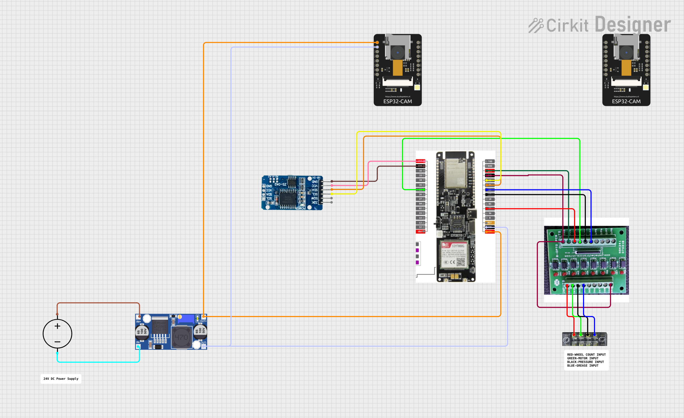
This circuit integrates a LilyGo-SIM7000G module with an RTC DS3231 for timekeeping, interfaced via I2C (SCL and SDA lines). An 8-Channel OPTO-COUPLER is used to isolate and interface external signals with the LilyGo-SIM7000G's GPIOs. Power is managed by a Buck converter, which steps down voltage from a DC Power Source to supply the ESP32-CAM and LilyGo-SIM7000G modules, as well as the OPTO-COUPLER.
Open Project in Cirkit DesignerESP8266 and SIM800L Based GPS Tracker with I2C LCD Display and Battery Power
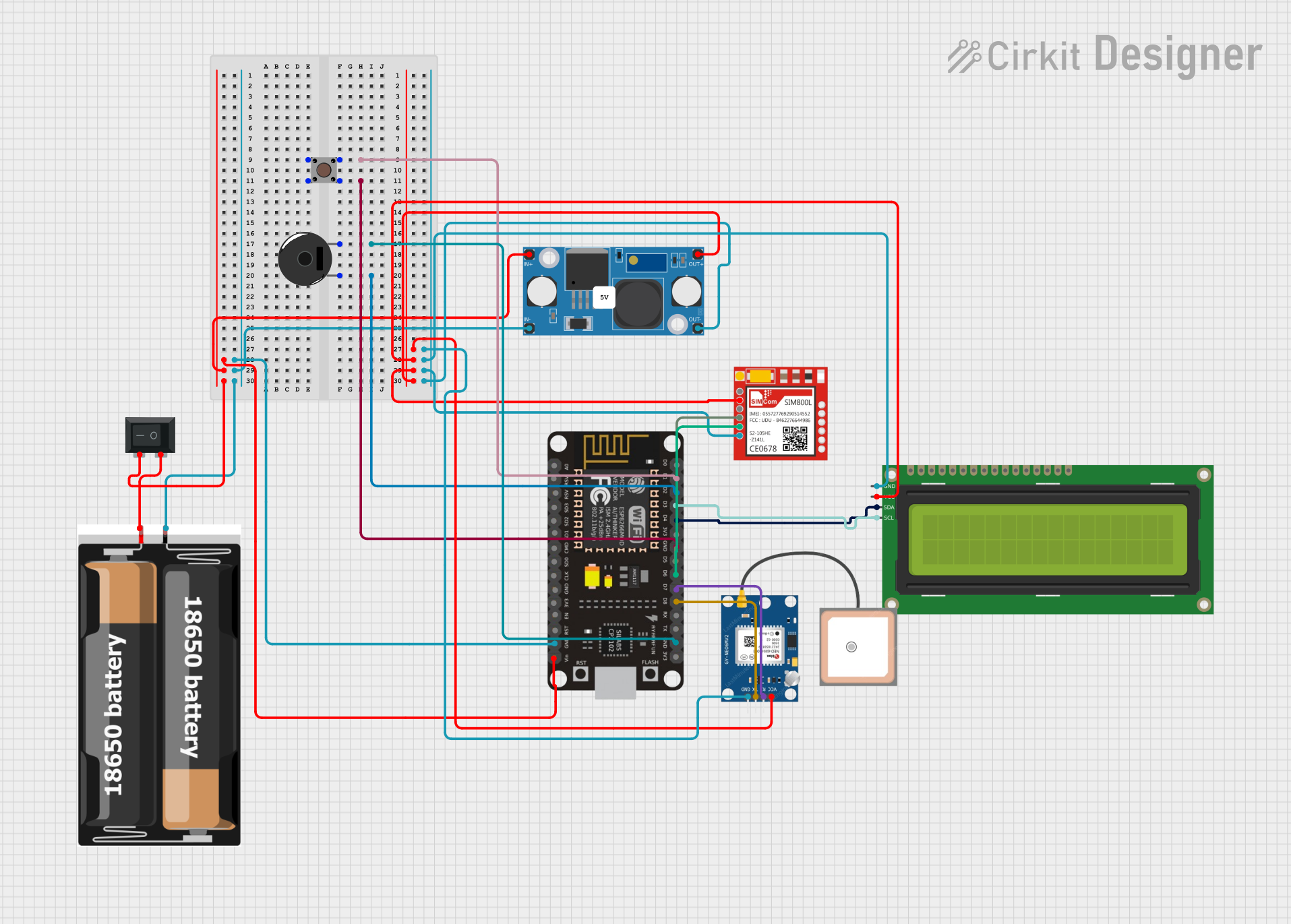
This circuit integrates an ESP8266 NodeMCU microcontroller with a SIM800L GSM module, a GPS NEO 6M module, and a 16x2 I2C LCD display for communication and location tracking. It also includes a pushbutton for user input, a piezo buzzer for audio alerts, and is powered by a 2x 18650 battery pack through an LM2596 step-down module.
Open Project in Cirkit DesignerCellular-Enabled IoT Device with Real-Time Clock and Power Management

This circuit features a LilyGo-SIM7000G module for cellular communication and GPS functionality, interfaced with an RTC DS3231 for real-time clock capabilities. It includes voltage sensing through two voltage sensor modules, and uses an 8-channel opto-coupler for isolating different parts of the circuit. Power management is handled by a buck converter connected to a DC power source and batteries, with a fuse for protection and a rocker switch for on/off control. Additionally, there's an LED for indication purposes.
Open Project in Cirkit DesignerExplore Projects Built with SC16IS752
STM32F103C8T6-Based Spectral Sensor with ST7735S Display and Pushbutton Control
This circuit features an STM32F103C8T6 microcontroller interfaced with a China ST7735S 160x128 display and two spectral sensors (Adafruit AS7262 and AS7261). It also includes two pushbuttons for user input, with the microcontroller managing the display and sensor data processing.
Open Project in Cirkit DesignerCellular-Connected ESP32-CAM with Real-Time Clock and Isolated Control
This circuit integrates a LilyGo-SIM7000G module with an RTC DS3231 for timekeeping, interfaced via I2C (SCL and SDA lines). An 8-Channel OPTO-COUPLER is used to isolate and interface external signals with the LilyGo-SIM7000G's GPIOs. Power is managed by a Buck converter, which steps down voltage from a DC Power Source to supply the ESP32-CAM and LilyGo-SIM7000G modules, as well as the OPTO-COUPLER.
Open Project in Cirkit DesignerESP8266 and SIM800L Based GPS Tracker with I2C LCD Display and Battery Power
This circuit integrates an ESP8266 NodeMCU microcontroller with a SIM800L GSM module, a GPS NEO 6M module, and a 16x2 I2C LCD display for communication and location tracking. It also includes a pushbutton for user input, a piezo buzzer for audio alerts, and is powered by a 2x 18650 battery pack through an LM2596 step-down module.
Open Project in Cirkit DesignerCellular-Enabled IoT Device with Real-Time Clock and Power Management
This circuit features a LilyGo-SIM7000G module for cellular communication and GPS functionality, interfaced with an RTC DS3231 for real-time clock capabilities. It includes voltage sensing through two voltage sensor modules, and uses an 8-channel opto-coupler for isolating different parts of the circuit. Power management is handled by a buck converter connected to a DC power source and batteries, with a fuse for protection and a rocker switch for on/off control. Additionally, there's an LED for indication purposes.
Open Project in Cirkit DesignerCommon Applications
- Industrial automation and control systems
- IoT devices requiring UART communication
- GPS modules and GSM modems
- Data logging and telemetry systems
- Multi-protocol communication bridges
Technical Specifications
Key Technical Details
- Supply Voltage (Vcc): 2.5V to 3.3V (5V tolerant I/O)
- Communication Protocols: I2C (up to 400 kHz) and SPI (up to 4 Mbps)
- UART Channels: 2 (dual UART)
- Baud Rate: Up to 5 Mbps
- FIFO Buffer: 64 bytes per channel (TX and RX)
- GPIO Pins: 8 configurable GPIOs
- Operating Temperature Range: -40°C to +85°C
- Package: TSSOP-28, HVQFN-32
Pin Configuration and Descriptions
The SC16IS752 is available in multiple packages. Below is the pin configuration for the TSSOP-28 package:
| Pin Number | Pin Name | Description |
|---|---|---|
| 1 | A0 | I2C address selection or SPI chip select (CS) |
| 2 | A1 | I2C address selection |
| 3 | RESET | Active-low reset input |
| 4 | XTAL1 | Crystal oscillator input or external clock input |
| 5 | XTAL2 | Crystal oscillator output |
| 6 | VSS | Ground |
| 7 | TXD0 | UART0 transmit data |
| 8 | RXD0 | UART0 receive data |
| 9 | RTS0 | UART0 request to send |
| 10 | CTS0 | UART0 clear to send |
| 11 | TXD1 | UART1 transmit data |
| 12 | RXD1 | UART1 receive data |
| 13 | RTS1 | UART1 request to send |
| 14 | CTS1 | UART1 clear to send |
| 15 | GPIO0 | General-purpose I/O pin |
| 16 | GPIO1 | General-purpose I/O pin |
| 17 | GPIO2 | General-purpose I/O pin |
| 18 | GPIO3 | General-purpose I/O pin |
| 19 | GPIO4 | General-purpose I/O pin |
| 20 | GPIO5 | General-purpose I/O pin |
| 21 | GPIO6 | General-purpose I/O pin |
| 22 | GPIO7 | General-purpose I/O pin |
| 23 | SCL/SCLK | I2C clock or SPI clock |
| 24 | SDA/MOSI | I2C data or SPI master out/slave in |
| 25 | MISO | SPI master in/slave out |
| 26 | IRQ | Interrupt request output |
| 27 | VCC | Power supply input |
| 28 | A2 | I2C address selection |
Usage Instructions
How to Use the SC16IS752 in a Circuit
- Power Supply: Connect the VCC pin to a 3.3V power source and the VSS pin to ground.
- Communication Protocol Selection:
- For I2C: Connect the SCL and SDA pins to the I2C bus of the microcontroller. Use A0, A1, and A2 to set the I2C address.
- For SPI: Connect SCLK, MOSI, MISO, and CS (A0) to the SPI bus of the microcontroller.
- UART Connections: Connect the TXD and RXD pins of each UART channel to the corresponding devices.
- GPIO Configuration: Use the GPIO pins as needed for additional control or status signals.
- Clock Source: Connect a crystal oscillator to XTAL1 and XTAL2, or provide an external clock signal to XTAL1.
- Interrupt Handling: Connect the IRQ pin to a microcontroller interrupt pin for efficient event handling.
Important Considerations
- Ensure proper pull-up resistors (typically 4.7kΩ) are used on the I2C bus lines (SCL and SDA).
- For SPI communication, ensure the clock polarity and phase settings match between the SC16IS752 and the microcontroller.
- Configure the baud rate and UART settings (e.g., parity, stop bits) to match the connected devices.
- Use decoupling capacitors (e.g., 0.1µF) near the VCC pin to stabilize the power supply.
Example Code for Arduino UNO (I2C Mode)
#include <Wire.h>

// SC16IS752 I2C address (A0, A1, A2 = 0)
#define SC16IS752_ADDR 0x48

void setup() {
  Wire.begin(); // Initialize I2C communication
  Serial.begin(9600); // Initialize Serial Monitor

  // Initialize SC16IS752
  Wire.beginTransmission(SC16IS752_ADDR);
  Wire.write(0x03); // Write to the FCR (FIFO Control Register)
  Wire.write(0x07); // Enable FIFO, clear TX/RX FIFO
  Wire.endTransmission();

  Serial.println("SC16IS752 Initialized");
}

void loop() {
  // Example: Send data to UART0
  Wire.beginTransmission(SC16IS752_ADDR);
  Wire.write(0x00); // THR (Transmit Holding Register) for UART0
  Wire.write('H');  // Send character 'H'
  Wire.endTransmission();

  delay(1000); // Wait 1 second
}
Troubleshooting and FAQs
Common Issues
No Communication with the SC16IS752:
- Verify the I2C or SPI connections and ensure the correct protocol is selected.
- Check the I2C address configuration (A0, A1, A2 pins).
- Ensure pull-up resistors are present on the I2C lines.
UART Data Loss:
- Ensure the baud rate and UART settings match between the SC16IS752 and the connected device.
- Check if the FIFO buffer is full and handle interrupts appropriately.
Interrupts Not Triggering:
- Verify the IRQ pin is connected to the correct microcontroller interrupt pin.
- Ensure the interrupt enable registers are configured correctly.
Tips for Troubleshooting
- Use an oscilloscope or logic analyzer to monitor I2C/SPI signals and UART data lines.
- Test the SC16IS752 with a simple loopback setup (connect TXD to RXD) to verify UART functionality.
- Refer to the SC16IS752 datasheet for detailed register descriptions and configuration options.