How to Use Double Pole 2POS rotory switch: Examples, Pinouts, and Specs
Introduction
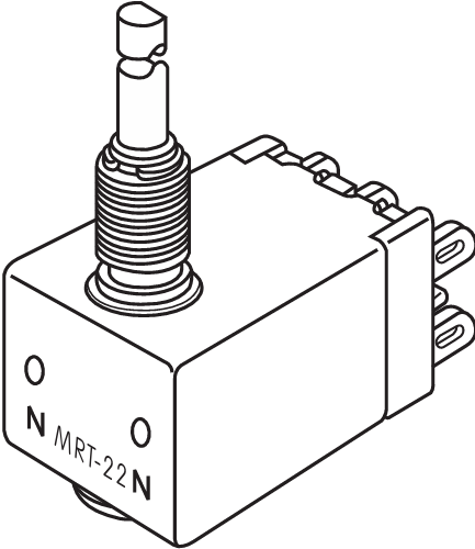
The Double Pole 2POS Rotary Switch (MRT22) by NKK Switches is a versatile component designed to control two separate circuits simultaneously. With its two-position functionality, it can be used for on/off operations or other switching functions. This rotary switch is commonly used in various applications, including audio equipment, industrial machinery, and control panels.
Explore Projects Built with Double Pole 2POS rotory switch

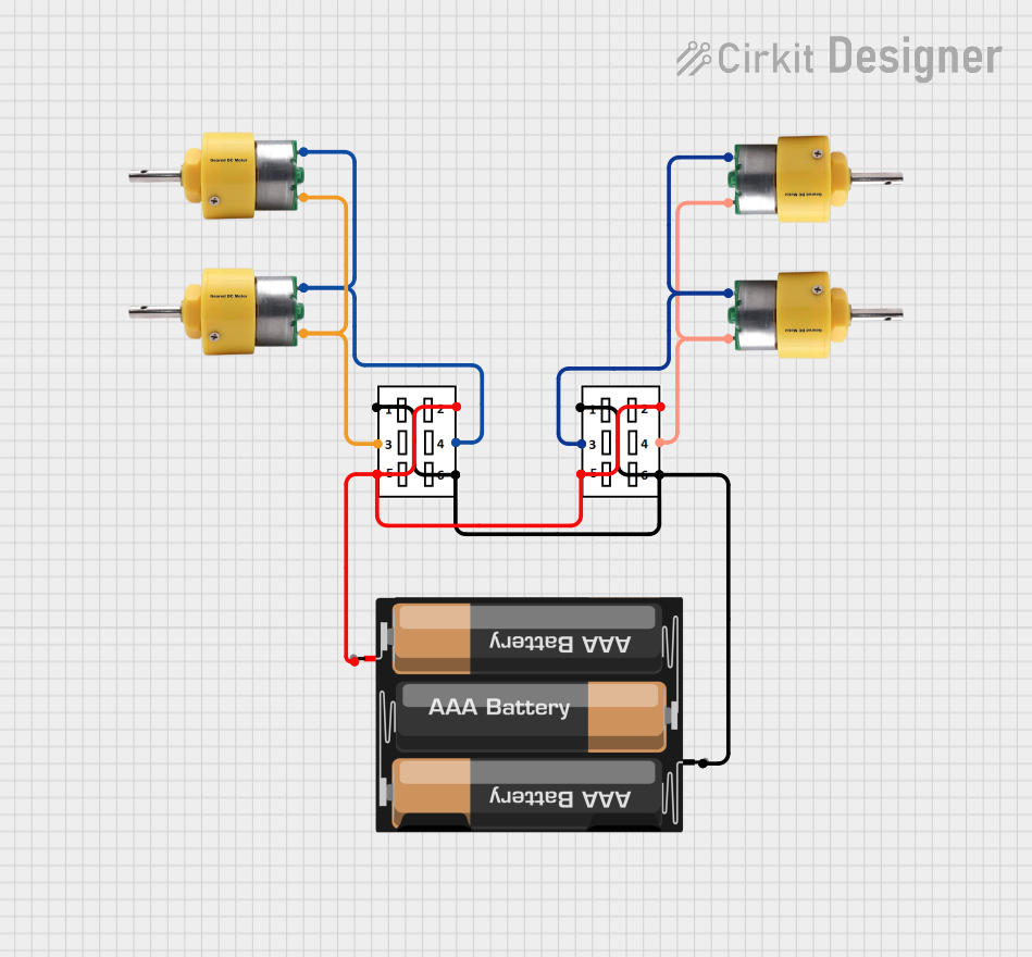

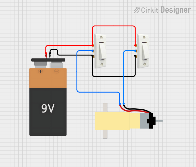
Explore Projects Built with Double Pole 2POS rotory switch
Technical Specifications
Key Technical Details
| Specification | Value |
|---|---|
| Manufacturer | NKK Switches |
| Part ID | MRT22 |
| Number of Poles | 2 |
| Number of Positions | 2 |
| Voltage Rating | 125V AC |
| Current Rating | 0.3A |
| Contact Resistance | 50 mΩ max |
| Insulation Resistance | 100 MΩ min at 500V DC |
| Dielectric Strength | 500V AC for 1 minute |
| Operating Temperature | -30°C to +85°C |
Pin Configuration and Descriptions
| Pin Number | Description |
|---|---|
| 1 | Pole 1 Common |
| 2 | Pole 1 Position 1 |
| 3 | Pole 1 Position 2 |
| 4 | Pole 2 Common |
| 5 | Pole 2 Position 1 |
| 6 | Pole 2 Position 2 |
Usage Instructions
How to Use the Component in a Circuit
- Identify the Pins: Refer to the pin configuration table to identify the common and position pins for each pole.
- Connect the Common Pins: Connect the common pins (Pin 1 for Pole 1 and Pin 4 for Pole 2) to the input voltage or signal source.
- Connect the Position Pins: Connect the position pins (Pins 2 and 3 for Pole 1, Pins 5 and 6 for Pole 2) to the respective output circuits.
- Mount the Switch: Securely mount the rotary switch on your control panel or circuit board.
Important Considerations and Best Practices
- Voltage and Current Ratings: Ensure that the voltage and current ratings of the switch are not exceeded to prevent damage.
- Debouncing: Implement debouncing techniques in your circuit to avoid false triggering due to mechanical bounce.
- Secure Connections: Make sure all connections are secure to avoid intermittent contact issues.
- Environmental Conditions: Consider the operating temperature range and ensure the switch is used within specified limits.
Example: Connecting to an Arduino UNO
To demonstrate the use of the MRT22 rotary switch with an Arduino UNO, we will create a simple circuit to read the switch positions and display the status on the serial monitor.
Circuit Diagram
Arduino UNO       MRT22 Rotary Switch
-----------       -------------------
  5V   ----------- Pin 1 (Pole 1 Common)
  GND  ----------- Pin 4 (Pole 2 Common)
  D2   ----------- Pin 2 (Pole 1 Position 1)
  D3   ----------- Pin 3 (Pole 1 Position 2)
  D4   ----------- Pin 5 (Pole 2 Position 1)
  D5   ----------- Pin 6 (Pole 2 Position 2)
Arduino Code
// Define pin connections
const int pole1Pos1 = 2;
const int pole1Pos2 = 3;
const int pole2Pos1 = 4;
const int pole2Pos2 = 5;

void setup() {
  // Initialize serial communication
  Serial.begin(9600);

  // Set pin modes
  pinMode(pole1Pos1, INPUT);
  pinMode(pole1Pos2, INPUT);
  pinMode(pole2Pos1, INPUT);
  pinMode(pole2Pos2, INPUT);
}

void loop() {
  // Read switch positions
  int pole1Pos1State = digitalRead(pole1Pos1);
  int pole1Pos2State = digitalRead(pole1Pos2);
  int pole2Pos1State = digitalRead(pole2Pos1);
  int pole2Pos2State = digitalRead(pole2Pos2);

  // Display switch positions on serial monitor
  Serial.print("Pole 1 Position 1: ");
  Serial.println(pole1Pos1State);
  Serial.print("Pole 1 Position 2: ");
  Serial.println(pole1Pos2State);
  Serial.print("Pole 2 Position 1: ");
  Serial.println(pole2Pos1State);
  Serial.print("Pole 2 Position 2: ");
  Serial.println(pole2Pos2State);

  // Add a small delay to avoid flooding the serial monitor
  delay(500);
}
Troubleshooting and FAQs
Common Issues Users Might Face
- Intermittent Contact: Loose connections can cause intermittent contact. Ensure all connections are secure.
- Incorrect Position Readings: Mechanical bounce can cause incorrect readings. Implement debouncing techniques in your circuit or code.
- Overheating: Exceeding the voltage or current ratings can cause the switch to overheat. Always operate within specified limits.
Solutions and Tips for Troubleshooting
- Check Connections: Verify that all connections are secure and correctly wired according to the pin configuration.
- Debounce: Use hardware or software debouncing techniques to filter out noise caused by mechanical bounce.
- Verify Ratings: Ensure that the voltage and current ratings are not exceeded to prevent damage to the switch.
FAQs
Q: Can the MRT22 switch be used for DC applications? A: Yes, the MRT22 switch can be used for both AC and DC applications, provided the voltage and current ratings are not exceeded.
Q: How do I implement debouncing in my circuit? A: Debouncing can be implemented using hardware (e.g., capacitors and resistors) or software (e.g., delay functions in code) techniques.
Q: What is the maximum operating temperature for the MRT22 switch? A: The maximum operating temperature for the MRT22 switch is +85°C.
This documentation provides a comprehensive guide to the Double Pole 2POS Rotary Switch (MRT22) by NKK Switches. Whether you are a beginner or an experienced user, this guide will help you understand, use, and troubleshoot this versatile component effectively.