
How to Use Parallax BASIC Stamp 2: Examples, Pinouts, and Specs
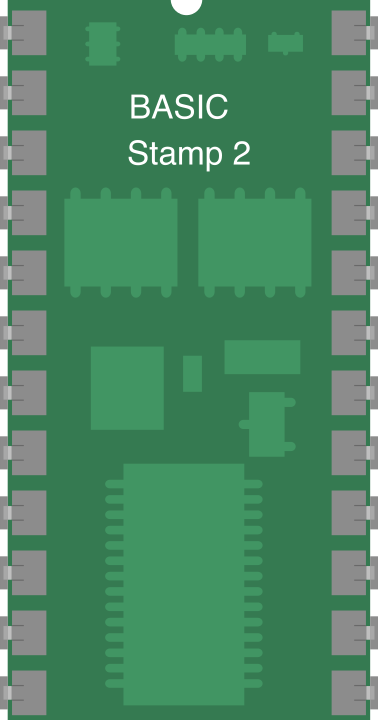
 Design with Parallax BASIC Stamp 2 in Cirkit Designer
Introduction
The Parallax BASIC Stamp 2 (BS2-IC) is a versatile microcontroller module designed for ease of use in programming and controlling electronic devices. It features a built-in interpreter for the BASIC programming language, making it an excellent choice for beginners and hobbyists. The BS2-IC is widely used in educational projects, prototyping, and small-scale automation systems due to its simplicity and reliability.
Explore Projects Built with Parallax BASIC Stamp 2
 Open Project in Cirkit Designer
 Open Project in Cirkit Designer
 Open Project in Cirkit Designer
 Open Project in Cirkit Designer
Explore Projects Built with Parallax BASIC Stamp 2
Open Project in Cirkit DesignerOpen Project in Cirkit DesignerOpen Project in Cirkit DesignerOpen Project in Cirkit DesignerCommon Applications and Use Cases
- Robotics and automation projects
- Educational tools for learning microcontroller programming
- Prototyping and proof-of-concept designs
- Home automation systems
- Sensor data acquisition and control
Technical Specifications
The following table outlines the key technical details of the Parallax BASIC Stamp 2:
| Specification | Details |
|---|---|
| Manufacturer | Parallax |
| Part Number | BS2-IC |
| Operating Voltage | 5V DC |
| Current Consumption | 3 mA (typical), 50 mA (max during I/O) |
| Clock Speed | 20 MHz |
| Program Memory | 2 KB EEPROM (500 instructions) |
| RAM | 32 Bytes |
| I/O Pins | 16 (TTL-compatible) |
| Communication Protocol | Serial (9600 baud) |
| Dimensions | 1.2" x 0.6" (30.5 mm x 15.2 mm) |
| Programming Language | PBASIC (Parallax BASIC) |
Pin Configuration and Descriptions
The BS2-IC module has a 24-pin DIP (Dual Inline Package) layout. Below is the pin configuration:
| Pin Number | Name | Description |
|---|---|---|
| 1 | VSS | Ground (0V) |
| 2 | VDD | +5V Power Supply |
| 3 | RES | Reset (Active Low) |
| 4-19 | P0-P15 | General Purpose I/O Pins (TTL-compatible) |
| 20 | ATN | Attention (used for programming) |
| 21-24 | NC | Not Connected |
Usage Instructions
How to Use the Component in a Circuit
- Power Supply: Connect the VDD pin to a regulated 5V power source and the VSS pin to ground.
- Programming: Use a serial cable or USB-to-serial adapter to connect the BS2-IC to your computer. The ATN pin is used during programming to reset the module.
- I/O Connections: Connect sensors, actuators, or other peripherals to the P0-P15 pins. These pins can be configured as input or output in your PBASIC code.
- Programming Environment: Download and install the Parallax BASIC Stamp Editor software from the Parallax website. Write your PBASIC code and upload it to the BS2-IC.
Important Considerations and Best Practices
- Power Supply: Ensure a stable 5V power supply to avoid erratic behavior.
- I/O Pin Current: Each I/O pin can source or sink up to 20 mA. Avoid exceeding this limit to prevent damage.
- Pull-up Resistors: Use pull-up or pull-down resistors for input pins to ensure stable readings.
- Decoupling Capacitor: Place a 0.1 µF capacitor between VDD and VSS to filter noise from the power supply.
Example Code for Arduino-like Functionality
Below is an example PBASIC code to blink an LED connected to pin P0:
' Blink an LED connected to P0
' Author: Parallax BASIC Stamp 2 Documentation

DO
  HIGH 0               ' Set P0 high to turn on the LED
  PAUSE 500            ' Wait for 500 milliseconds
  LOW 0                ' Set P0 low to turn off the LED
  PAUSE 500            ' Wait for 500 milliseconds
LOOP
Interfacing with Sensors
To read a digital sensor connected to P1, you can use the following PBASIC code:
' Read a digital sensor connected to P1
' Author: Parallax BASIC Stamp 2 Documentation

INPUT 1                ' Configure P1 as an input
DO
  IF IN1 = 1 THEN      ' Check if the sensor output is HIGH
    DEBUG "Sensor is active", CR
  ELSE
    DEBUG "Sensor is inactive", CR
  ENDIF
  PAUSE 1000           ' Wait for 1 second before reading again
LOOP
Troubleshooting and FAQs
Common Issues and Solutions
Module Not Responding to Programming:
- Ensure the ATN pin is properly connected.
- Verify that the serial cable or USB-to-serial adapter is functioning correctly.
- Check the power supply voltage (must be 5V).
Erratic Behavior:
- Add a decoupling capacitor (0.1 µF) between VDD and VSS.
- Ensure that the I/O pins are not overloaded (max 20 mA per pin).
Incorrect Sensor Readings:
- Use pull-up or pull-down resistors for input pins.
- Verify the sensor's power supply and connections.
Program Memory Full:
- Optimize your PBASIC code by removing unnecessary instructions.
- Use subroutines to reduce code duplication.
FAQs
Q: Can the BS2-IC handle analog inputs?
A: No, the BS2-IC does not have built-in analog-to-digital conversion. You can use an external ADC module to interface with analog sensors.
Q: What is the maximum cable length for serial communication?
A: The maximum cable length depends on the baud rate and cable quality. For 9600 baud, a length of up to 50 feet is typically reliable.
Q: Can I use the BS2-IC with a breadboard?
A: Yes, the 24-pin DIP package is breadboard-friendly, making it easy to prototype circuits.
Q: Is the BS2-IC compatible with Arduino shields?
A: No, the BS2-IC is not directly compatible with Arduino shields due to differences in pin layout and functionality. However, you can manually wire connections to use certain shields.
This concludes the documentation for the Parallax BASIC Stamp 2 (BS2-IC). For further assistance, refer to the official Parallax resources or community forums.