
How to Use Contactor Sirius: Examples, Pinouts, and Specs
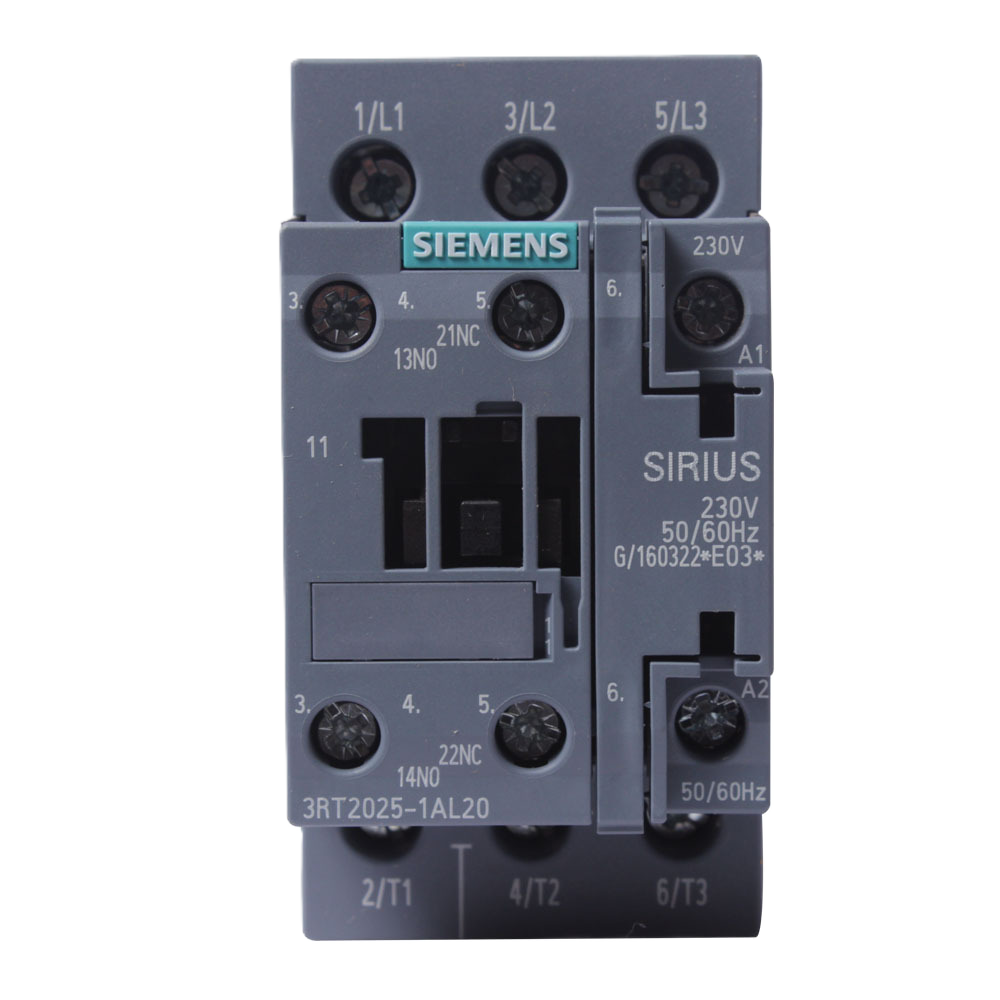
 Design with Contactor Sirius in Cirkit Designer
Introduction
The Contactor Sirius (Manufacturer Part ID: 2) by Siemens is an electromechanical switch designed to control the flow of electricity in a circuit. It is widely used in industrial automation systems to enable or disable power to motors, lighting systems, and other electrical devices. Known for its high reliability and robust performance, the Contactor Sirius is ideal for applications requiring frequent switching and high current handling.
Explore Projects Built with Contactor Sirius
 Open Project in Cirkit Designer
 Open Project in Cirkit Designer
 Open Project in Cirkit Designer
 Open Project in Cirkit Designer
Explore Projects Built with Contactor Sirius
Open Project in Cirkit DesignerOpen Project in Cirkit DesignerOpen Project in Cirkit DesignerOpen Project in Cirkit DesignerCommon Applications and Use Cases
- Motor control in industrial automation systems
- Switching of lighting circuits in commercial buildings
- Power distribution and load management
- Integration into programmable logic controllers (PLCs) for automated systems
- HVAC systems for controlling compressors and fans
Technical Specifications
The following table outlines the key technical specifications of the Contactor Sirius:
| Parameter | Value |
|---|---|
| Manufacturer | Siemens |
| Part ID | 2 |
| Rated Operational Voltage | Up to 690 V AC |
| Rated Operational Current | Up to 38 A (depending on model) |
| Control Voltage | 24 V DC / 230 V AC (varies by model) |
| Number of Poles | 3 (standard) |
| Mechanical Durability | Up to 10 million operations |
| Electrical Durability | Up to 1 million operations |
| Operating Temperature Range | -25°C to +60°C |
| Mounting Type | DIN rail or screw mounting |
| Standards Compliance | IEC 60947, UL 508, CSA C22.2 |
Pin Configuration and Descriptions
The Contactor Sirius typically features the following terminal configuration:
| Terminal | Description |
|---|---|
| L1, L2, L3 | Input terminals for the three-phase power supply |
| T1, T2, T3 | Output terminals for the load (e.g., motor) |
| A1, A2 | Coil terminals for control voltage |
| NO (Normally Open) | Auxiliary contact for additional control circuits |
| NC (Normally Closed) | Auxiliary contact for additional control circuits |
Usage Instructions
How to Use the Contactor Sirius in a Circuit
- Power Supply Connection: Connect the three-phase power supply to the input terminals (L1, L2, L3).
- Load Connection: Connect the load (e.g., motor) to the output terminals (T1, T2, T3).
- Control Circuit: Apply the appropriate control voltage to the coil terminals (A1, A2) to energize the contactor.
- Auxiliary Contacts: Use the auxiliary contacts (NO/NC) for additional control or feedback in your circuit.
Important Considerations and Best Practices
- Voltage and Current Ratings: Ensure the contactor's voltage and current ratings match the requirements of your application.
- Control Voltage: Verify that the control voltage applied to the coil matches the specifications (e.g., 24 V DC or 230 V AC).
- Overload Protection: Use appropriate overload relays or circuit breakers to protect the contactor and connected devices.
- Mounting: Securely mount the contactor on a DIN rail or with screws to prevent vibration or movement.
- Wiring: Use properly rated wires and ensure all connections are tight to avoid overheating or arcing.
Example: Connecting the Contactor Sirius to an Arduino UNO
The Contactor Sirius can be controlled using an Arduino UNO by interfacing the control coil with a relay module. Below is an example code snippet:
// Example: Controlling the Contactor Sirius with Arduino UNO
// This code toggles the contactor ON and OFF every 5 seconds.

const int relayPin = 7; // Pin connected to the relay module

void setup() {
  pinMode(relayPin, OUTPUT); // Set relayPin as an output
  digitalWrite(relayPin, LOW); // Ensure the relay is initially OFF
}

void loop() {
  digitalWrite(relayPin, HIGH); // Turn ON the relay (energize contactor)
  delay(5000); // Wait for 5 seconds
  digitalWrite(relayPin, LOW); // Turn OFF the relay (de-energize contactor)
  delay(5000); // Wait for 5 seconds
}
Note: Use a relay module to interface the Arduino with the Contactor Sirius, as the Arduino cannot directly supply the required control voltage or current.
Troubleshooting and FAQs
Common Issues and Solutions
Contactor Does Not Energize:
- Cause: Incorrect control voltage or loose connections.
- Solution: Verify the control voltage at terminals A1 and A2. Check all wiring connections.
Excessive Heating:
- Cause: Overloaded contactor or loose terminal connections.
- Solution: Ensure the load does not exceed the contactor's rated current. Tighten all connections.
Chattering Noise:
- Cause: Insufficient control voltage or unstable power supply.
- Solution: Check the control voltage and ensure it is stable and within the specified range.
Auxiliary Contacts Not Functioning:
- Cause: Miswiring or damaged auxiliary contacts.
- Solution: Verify the wiring of the auxiliary contacts. Replace if damaged.
FAQs
Q1: Can the Contactor Sirius be used for single-phase applications?
A1: Yes, the Contactor Sirius can be used for single-phase applications by connecting only one input and one output terminal.
Q2: How do I select the right Contactor Sirius model for my application?
A2: Consider the operational voltage, current, and control voltage requirements of your application. Refer to Siemens' product catalog for detailed selection guidance.
Q3: Can I use the Contactor Sirius in outdoor environments?
A3: The Contactor Sirius is designed for indoor use. For outdoor applications, ensure it is installed in a weatherproof enclosure.
Q4: What is the lifespan of the Contactor Sirius?
A4: The mechanical durability is up to 10 million operations, while the electrical durability is up to 1 million operations, depending on the load and usage conditions.