How to Use USB type A Female: Examples, Pinouts, and Specs
Introduction
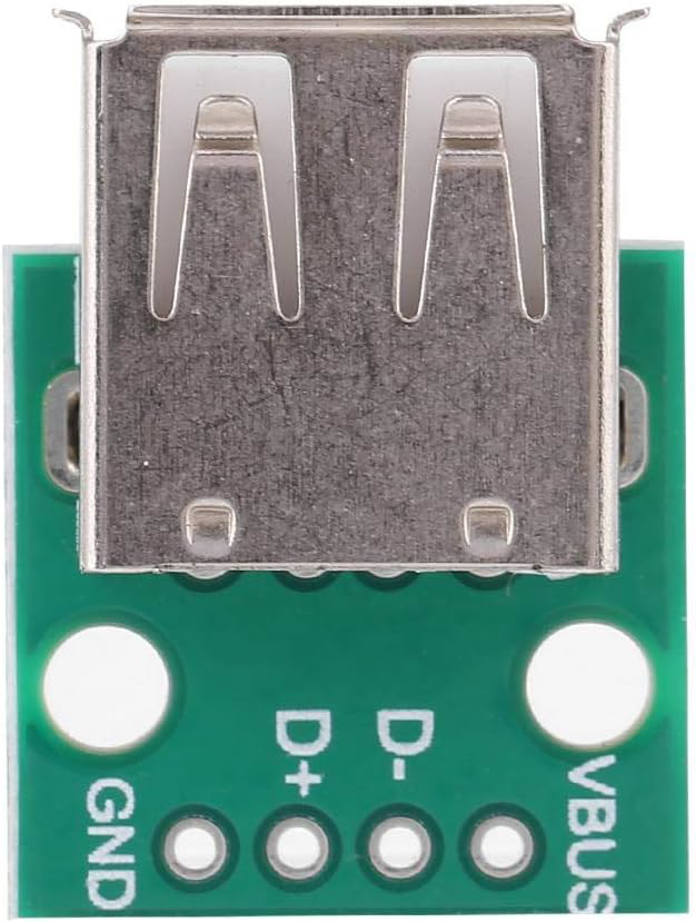
The USB Type A Female connector (Part ID: nk2) is a standard interface widely used for connecting peripheral devices to a host, such as computers, laptops, and chargers. It supports both data transfer and power supply, making it a versatile component in modern electronics. This connector is commonly found in USB hubs, power adapters, and embedded systems requiring USB connectivity.
Explore Projects Built with USB type A Female


Explore Projects Built with USB type A Female
Common Applications
- Connecting USB devices (e.g., keyboards, mice, flash drives) to a host.
- Power delivery for devices such as smartphones, tablets, and IoT devices.
- Integration into custom electronics projects for USB communication.
- USB extension cables and adapters.
Technical Specifications
Key Technical Details
- Connector Type: USB Type A Female
- Voltage Rating: 5V DC (standard USB voltage)
- Current Rating: Up to 2A (depending on the USB version and application)
- Data Transfer Rates:
- USB 2.0: Up to 480 Mbps
- USB 3.0: Up to 5 Gbps (if applicable)
- Operating Temperature: -20°C to 70°C
- Durability: Rated for 1,500+ insertion/removal cycles
- Mounting Style: Through-hole or surface mount (varies by design)
Pin Configuration and Descriptions
The USB Type A Female connector has four or more pins, depending on the USB version. Below is the pinout for USB 2.0:
| Pin Number | Name | Description |
|---|---|---|
| 1 | VBUS | +5V Power Supply |
| 2 | D- | Data Line (negative) |
| 3 | D+ | Data Line (positive) |
| 4 | GND | Ground |
For USB 3.0, additional pins are included for SuperSpeed data transfer:
| Pin Number | Name | Description |
|---|---|---|
| 5 | StdA_SSRX- | SuperSpeed Receiver (negative) |
| 6 | StdA_SSRX+ | SuperSpeed Receiver (positive) |
| 7 | GND_DRAIN | Ground for SuperSpeed signal pairs |
| 8 | StdA_SSTX- | SuperSpeed Transmitter (negative) |
| 9 | StdA_SSTX+ | SuperSpeed Transmitter (positive) |
Usage Instructions
How to Use the Component in a Circuit
- Mounting the Connector:
- If using a through-hole version, solder the pins to the PCB pads.
- For surface-mount versions, ensure proper alignment and soldering using reflow techniques.
- Power Connections:
- Connect the VBUS pin to a regulated 5V power source.
- Connect the GND pin to the circuit's ground.
- Data Connections:
- Connect the D+ and D- pins to the corresponding data lines of the host controller.
- For USB 3.0, also connect the SuperSpeed pins (if applicable).
- Mechanical Support:
- Secure the connector to the PCB using screws or soldered mounting tabs to ensure durability.
Important Considerations and Best Practices
- Voltage Regulation: Ensure the power supply to the VBUS pin is stable and within the 5V range to avoid damaging connected devices.
- Signal Integrity: Use short, low-impedance traces for the D+ and D- lines to minimize noise and signal degradation.
- ESD Protection: Add ESD protection diodes on the data lines to safeguard against electrostatic discharge.
- USB Compliance: Follow USB standards for trace impedance and routing to ensure compatibility with USB devices.
Example: Connecting to an Arduino UNO
The USB Type A Female connector can be used to interface USB devices with an Arduino UNO. Below is an example of wiring and code for reading data from a USB keyboard using a USB Host Shield.
Wiring
- Connect the VBUS pin of the USB connector to the 5V pin on the Arduino.
- Connect the GND pin of the USB connector to the GND pin on the Arduino.
- Connect the D+ and D- pins to the corresponding pins on the USB Host Shield.
Code Example
#include <USBHost.h> // Include USB Host library

USBHost usb;          // Create USBHost object
KeyboardController keyboard(usb); // Create KeyboardController object

void setup() {
  Serial.begin(9600); // Initialize serial communication
  while (!Serial) {
    ; // Wait for serial port to connect
  }
  Serial.println("USB Host Shield Initialized");
  usb.begin(); // Start USB host
}

void loop() {
  usb.Task(); // Process USB tasks
  if (keyboard.available()) {
    char key = keyboard.getKey(); // Get key pressed
    Serial.print("Key Pressed: ");
    Serial.println(key);
  }
}
Note: This example requires a USB Host Shield and the USB Host library.
Troubleshooting and FAQs
Common Issues
No Power to Connected Device:
- Cause: VBUS pin not properly connected to a 5V source.
- Solution: Verify the power supply and ensure proper soldering of the VBUS pin.
Data Transfer Fails:
- Cause: Incorrect wiring of D+ and D- pins or excessive noise on data lines.
- Solution: Check the connections and use proper shielding for data lines.
Device Not Recognized:
- Cause: Non-compliance with USB standards or damaged connector.
- Solution: Verify the circuit design and replace the connector if necessary.
FAQs
Can this connector handle USB 3.0 speeds?
- Yes, if the connector includes the additional SuperSpeed pins and is used with compatible devices.
What is the maximum current this connector can handle?
- The connector can handle up to 2A, depending on the application and USB version.
Is this connector suitable for outdoor use?
- No, unless additional weatherproofing measures are taken.
Can I use this connector for charging only?
- Yes, you can use the VBUS and GND pins for power delivery without connecting the data lines.
By following this documentation, users can effectively integrate the USB Type A Female connector into their projects for reliable data and power connections.