How to Use CAN: Examples, Pinouts, and Specs
Introduction
The Controller Area Network (CAN) is a robust vehicle bus standard designed to enable efficient communication between microcontrollers and devices without requiring a host computer. Originally developed for automotive applications, CAN has become a widely adopted protocol in various industries due to its reliability, real-time capabilities, and fault tolerance. It is particularly well-suited for environments where multiple devices need to exchange data efficiently and securely.
Explore Projects Built with CAN
Explore Projects Built with CAN
Common Applications and Use Cases
- Automotive Systems: Engine control units (ECUs), anti-lock braking systems (ABS), and airbag systems.
- Industrial Automation: Factory machinery and robotics.
- Medical Devices: Communication between sensors and control units in medical equipment.
- Aerospace: Avionics systems and in-flight data communication.
- IoT and Embedded Systems: Communication between sensors, actuators, and controllers.
Technical Specifications
The CAN protocol is defined by the ISO 11898 standard and operates on a two-wire differential signaling system. Below are the key technical details:
Key Technical Details
- Voltage Levels: 3.3V or 5V (depending on the transceiver used)
- Data Rate: Up to 1 Mbps (Classical CAN); up to 5 Mbps (CAN FD - Flexible Data-rate)
- Bus Length: Up to 40 meters at 1 Mbps; longer distances possible at lower data rates
- Number of Nodes: Up to 120 nodes on a single CAN bus
- Error Detection: Cyclic Redundancy Check (CRC), bit stuffing, and acknowledgment
- Message Frame Types: Data frame, remote frame, error frame, and overload frame
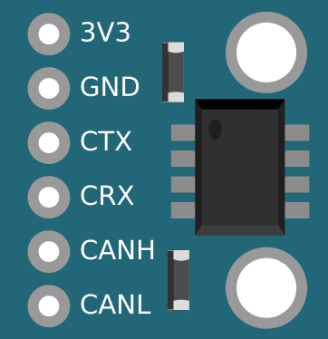
Pin Configuration and Descriptions
The CAN bus typically uses a transceiver IC (e.g., MCP2551 or TJA1050) to interface with the microcontroller. Below is the pin configuration for a common CAN transceiver:
| Pin | Name | Description |
|---|---|---|
| 1 | TXD | Transmit data input from the microcontroller |
| 2 | RXD | Receive data output to the microcontroller |
| 3 | VCC | Power supply (typically 5V or 3.3V) |
| 4 | GND | Ground connection |
| 5 | CANH | CAN High - Differential signal line for the CAN bus |
| 6 | CANL | CAN Low - Differential signal line for the CAN bus |
| 7 | RS (optional) | Mode selection pin (e.g., high-speed, standby, or slope control, depending on IC) |
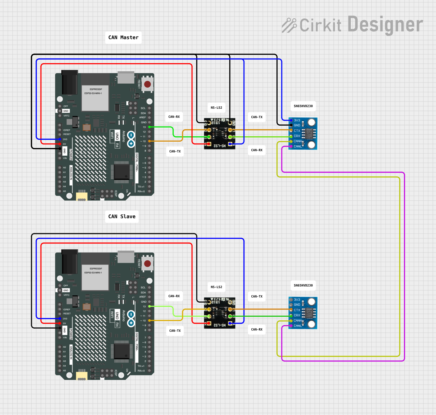
Usage Instructions
How to Use the Component in a Circuit
- Connect the Transceiver: Use a CAN transceiver IC to interface the microcontroller with the CAN bus. Connect the TXD and RXD pins of the transceiver to the corresponding UART or CAN controller pins on the microcontroller.
- Connect the CAN Bus: Attach the CANH and CANL pins of the transceiver to the CAN bus. Ensure proper termination resistors (typically 120 ohms) are placed at both ends of the bus to prevent signal reflections.
- Power the Circuit: Provide the required voltage (3.3V or 5V) to the VCC pin of the transceiver and connect the GND pin to the circuit ground.
- Configure the Microcontroller: Initialize the CAN controller on the microcontroller with the desired baud rate and message filters.
- Send and Receive Messages: Use the microcontroller to send and receive CAN messages via the transceiver.
Important Considerations and Best Practices
- Termination Resistors: Always use 120-ohm resistors at both ends of the CAN bus to ensure signal integrity.
- Baud Rate Matching: Ensure all nodes on the CAN bus are configured to use the same baud rate.
- Shielded Cables: Use shielded twisted-pair cables for the CANH and CANL lines in noisy environments.
- Error Handling: Implement error-handling routines to manage bus errors and retransmissions.
- Isolation: For high-voltage or noisy environments, consider using galvanic isolation between the CAN transceiver and the microcontroller.
Example Code for Arduino UNO
Below is an example of how to use an MCP2515 CAN module with an Arduino UNO to send a CAN message:
#include <SPI.h>
#include <mcp_can.h>

// Define the SPI CS pin for the MCP2515 module
#define CAN_CS_PIN 10

// Initialize the MCP_CAN object
MCP_CAN CAN(CAN_CS_PIN);

void setup() {
  Serial.begin(115200); // Initialize serial communication for debugging
  while (!Serial);

  // Initialize the CAN bus at 500 kbps
  if (CAN.begin(MCP_ANY, 500000, MCP_8MHZ) == CAN_OK) {
    Serial.println("CAN bus initialized successfully!");
  } else {
    Serial.println("CAN bus initialization failed!");
    while (1);
  }

  CAN.setMode(MCP_NORMAL); // Set the CAN module to normal mode
  Serial.println("CAN module set to normal mode.");
}

void loop() {
  // Define a sample CAN message
  unsigned char message[8] = {0x01, 0x02, 0x03, 0x04, 0x05, 0x06, 0x07, 0x08};

  // Send the CAN message with ID 0x100
  if (CAN.sendMsgBuf(0x100, 0, 8, message) == CAN_OK) {
    Serial.println("Message sent successfully!");
  } else {
    Serial.println("Error sending message.");
  }

  delay(1000); // Wait 1 second before sending the next message
}
Troubleshooting and FAQs
Common Issues and Solutions
No Communication on the CAN Bus
- Cause: Missing or incorrect termination resistors.
- Solution: Ensure 120-ohm resistors are placed at both ends of the CAN bus.
CAN Bus Initialization Fails
- Cause: Incorrect baud rate or wiring issues.
- Solution: Verify that all nodes are configured with the same baud rate and check the wiring.
High Error Rates
- Cause: Electrical noise or improper grounding.
- Solution: Use shielded cables and ensure proper grounding of all devices.
Message Collisions
- Cause: Multiple nodes transmitting simultaneously.
- Solution: The CAN protocol handles collisions automatically. Ensure proper message prioritization using the identifier field.
FAQs
Q: Can I use the CAN protocol for long-distance communication?
- A: Yes, but the maximum distance depends on the baud rate. For example, at 1 Mbps, the maximum distance is approximately 40 meters. Lower baud rates allow for longer distances.
Q: Do I need a specific microcontroller to use CAN?
- A: No, but the microcontroller must have a built-in CAN controller or be used with an external CAN controller (e.g., MCP2515).
Q: What happens if a node fails on the CAN bus?
- A: The CAN protocol is designed to be fault-tolerant. Other nodes will continue to communicate, and the failed node can be isolated.
This documentation provides a comprehensive guide to understanding and using the Controller Area Network (CAN) in various applications.