How to Use LTC4311: Examples, Pinouts, and Specs
Introduction
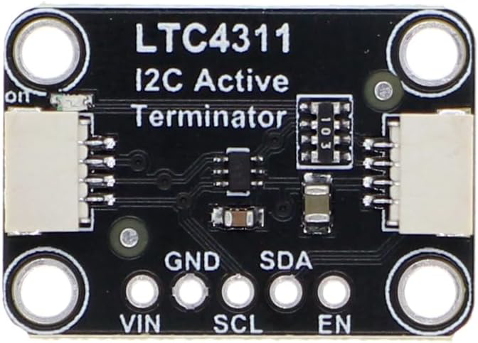
The LTC4311, manufactured by Adafruit, is a high-speed I2C bus extender designed to enhance the communication range and reliability of I2C devices. It operates by buffering the I2C signals, allowing for longer bus lengths and higher data rates of up to 1 MHz. This makes it an ideal solution for applications where I2C devices are distributed over significant distances or where signal integrity is critical.
Explore Projects Built with LTC4311


Explore Projects Built with LTC4311
Common Applications and Use Cases
- Industrial automation systems with distributed sensors and controllers
- Robotics with multiple I2C peripherals
- Long-distance communication between microcontrollers and I2C devices
- High-speed data acquisition systems
- Consumer electronics requiring reliable I2C communication over extended distances
Technical Specifications
The following table outlines the key technical details of the LTC4311:
| Parameter | Value |
|---|---|
| Operating Voltage Range | 2.7V to 5.5V |
| Maximum Data Rate | 1 MHz |
| Operating Temperature Range | -40°C to 85°C |
| Input Capacitance | 10 pF (typical) |
| Propagation Delay | 0.5 µs (typical) |
| Supply Current | 1.5 mA (typical) |
| Package Type | 6-pin SOT-23 |
Pin Configuration and Descriptions
The LTC4311 is available in a 6-pin SOT-23 package. The pinout and descriptions are as follows:
| Pin | Name | Description |
|---|---|---|
| 1 | VCC | Power supply input (2.7V to 5.5V). Connect to the system's power supply. |
| 2 | GND | Ground reference for the device. Connect to the system ground. |
| 3 | EN | Enable pin. Pull high to enable the LTC4311 or low to disable it. |
| 4 | SDAIN | Serial Data Input. Connect to the SDA line of the I2C bus. |
| 5 | SCLIN | Serial Clock Input. Connect to the SCL line of the I2C bus. |
| 6 | OUT | Buffered output for both SDA and SCL lines. Connect to the extended I2C bus. |
Usage Instructions
How to Use the LTC4311 in a Circuit
- Power Supply: Connect the VCC pin to a power supply within the range of 2.7V to 5.5V. Ensure the GND pin is connected to the system ground.
- I2C Bus Connection:
- Connect the SDAIN and SCLIN pins to the SDA and SCL lines of the primary I2C bus.
- Connect the OUT pin to the extended I2C bus where additional devices are located.
- Enable the Device: Pull the EN pin high to activate the LTC4311. If the EN pin is pulled low, the device will be disabled.
- Pull-Up Resistors: Ensure appropriate pull-up resistors are present on both the primary and extended I2C buses. The LTC4311 does not include internal pull-ups.
- Data Rate: Verify that the I2C bus operates at a data rate of 1 MHz or lower to ensure compatibility.
Important Considerations and Best Practices
- Signal Integrity: Use proper PCB layout techniques to minimize noise and ensure clean signal transmission.
- Bus Capacitance: The LTC4311 helps reduce the effects of bus capacitance, but ensure the total capacitance does not exceed I2C specifications.
- Enable Pin Control: Use a microcontroller GPIO pin to control the EN pin for dynamic enabling/disabling of the LTC4311.
- Power Supply Decoupling: Place a 0.1 µF ceramic capacitor close to the VCC pin to filter noise and stabilize the power supply.
Example: Using the LTC4311 with an Arduino UNO
Below is an example of how to connect and use the LTC4311 with an Arduino UNO to extend an I2C bus:
Circuit Diagram
- Connect the Arduino's SDA (A4) and SCL (A5) pins to the SDAIN and SCLIN pins of the LTC4311.
- Connect the OUT pin of the LTC4311 to the extended I2C bus.
- Pull the EN pin high using a 10 kΩ resistor or connect it to a GPIO pin for control.
Arduino Code Example
#include <Wire.h> // Include the Wire library for I2C communication

void setup() {
  Wire.begin(); // Initialize the I2C bus
  Serial.begin(9600); // Start serial communication for debugging

  // Optional: Enable the LTC4311 via a GPIO pin
  pinMode(7, OUTPUT); // Set pin 7 as output
  digitalWrite(7, HIGH); // Pull the EN pin high to enable the LTC4311

  Serial.println("LTC4311 enabled and I2C bus initialized.");
}

void loop() {
  // Example: Communicate with an I2C device at address 0x40
  Wire.beginTransmission(0x40); // Start communication with the device
  Wire.write(0x01); // Send a command or data
  Wire.endTransmission(); // End the transmission

  delay(1000); // Wait for 1 second before repeating
}
Troubleshooting and FAQs
Common Issues and Solutions
No Communication on the Extended Bus:
- Ensure the EN pin is pulled high to enable the LTC4311.
- Verify that pull-up resistors are present on both the primary and extended I2C buses.
- Check the connections for continuity and ensure there are no loose wires.
Data Corruption or Noise:
- Use shorter wires and proper shielding to reduce noise.
- Verify that the total bus capacitance is within the I2C specification limits.
Device Overheating:
- Ensure the supply voltage does not exceed 5.5V.
- Check for excessive current draw due to incorrect wiring or a short circuit.
I2C Bus Not Operating at 1 MHz:
- Confirm that all devices on the bus support the desired data rate.
- Check the pull-up resistor values to ensure proper rise times.
FAQs
Q: Can the LTC4311 be used with 3.3V and 5V I2C devices on the same bus?
A: No, the LTC4311 does not perform voltage level translation. Use a dedicated level shifter if your I2C devices operate at different voltage levels.
Q: How far can the I2C bus be extended using the LTC4311?
A: The maximum distance depends on factors such as wire quality, bus capacitance, and data rate. The LTC4311 significantly improves the range, but testing in your specific application is recommended.
Q: Do I need pull-up resistors on both sides of the LTC4311?
A: Yes, pull-up resistors are required on both the primary and extended I2C buses for proper operation.
Q: Can I use multiple LTC4311 devices on the same I2C bus?
A: Yes, multiple LTC4311 devices can be used to extend different segments of the I2C bus, but ensure proper bus termination and signal integrity.