How to Use Smart House Controller Board: Examples, Pinouts, and Specs
Introduction
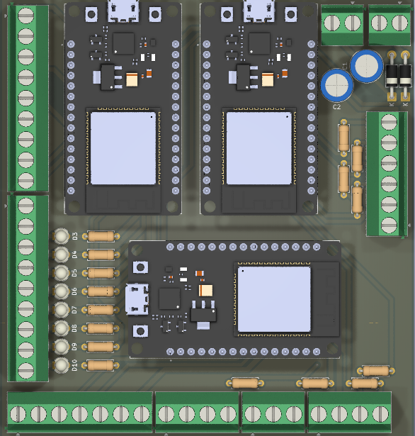
The Smart House Controller Board by SYD is a versatile and powerful central hub designed to manage and control various smart devices in a home. It enables seamless automation, real-time monitoring, and remote access through an intuitive user interface. This board is ideal for creating a connected smart home ecosystem, offering compatibility with a wide range of sensors, actuators, and communication protocols.
Explore Projects Built with Smart House Controller Board
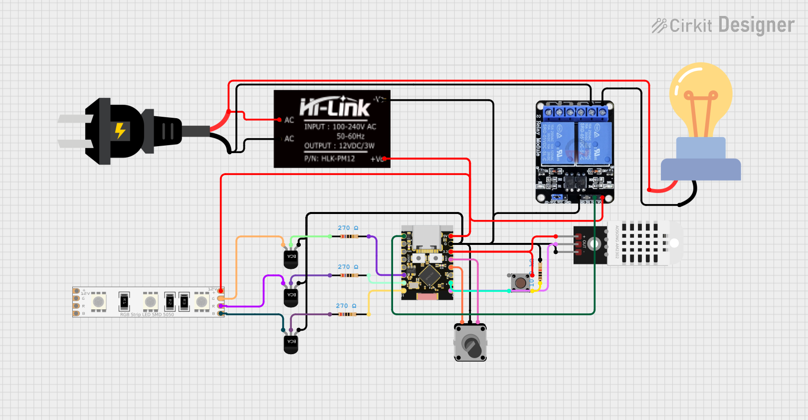
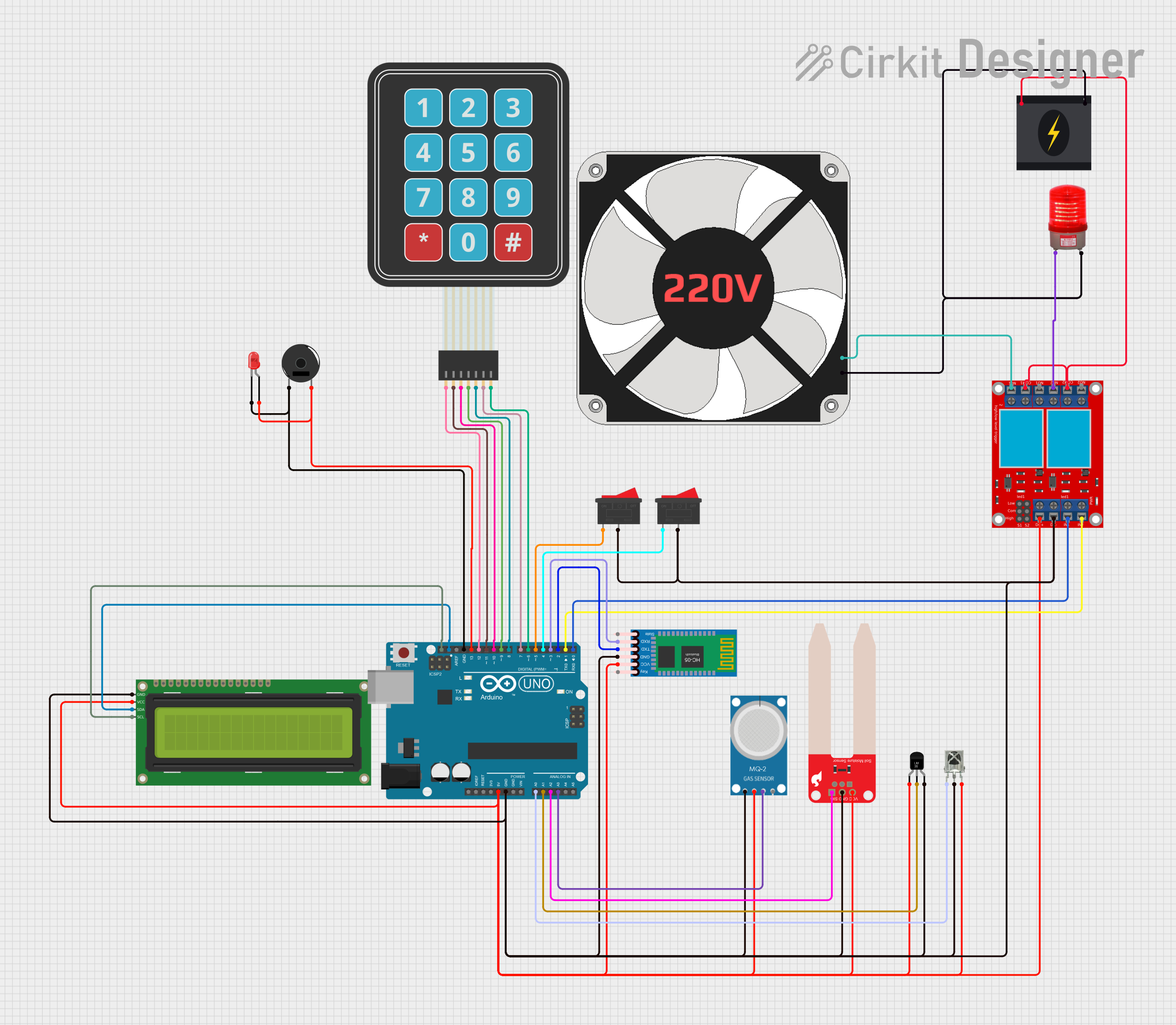

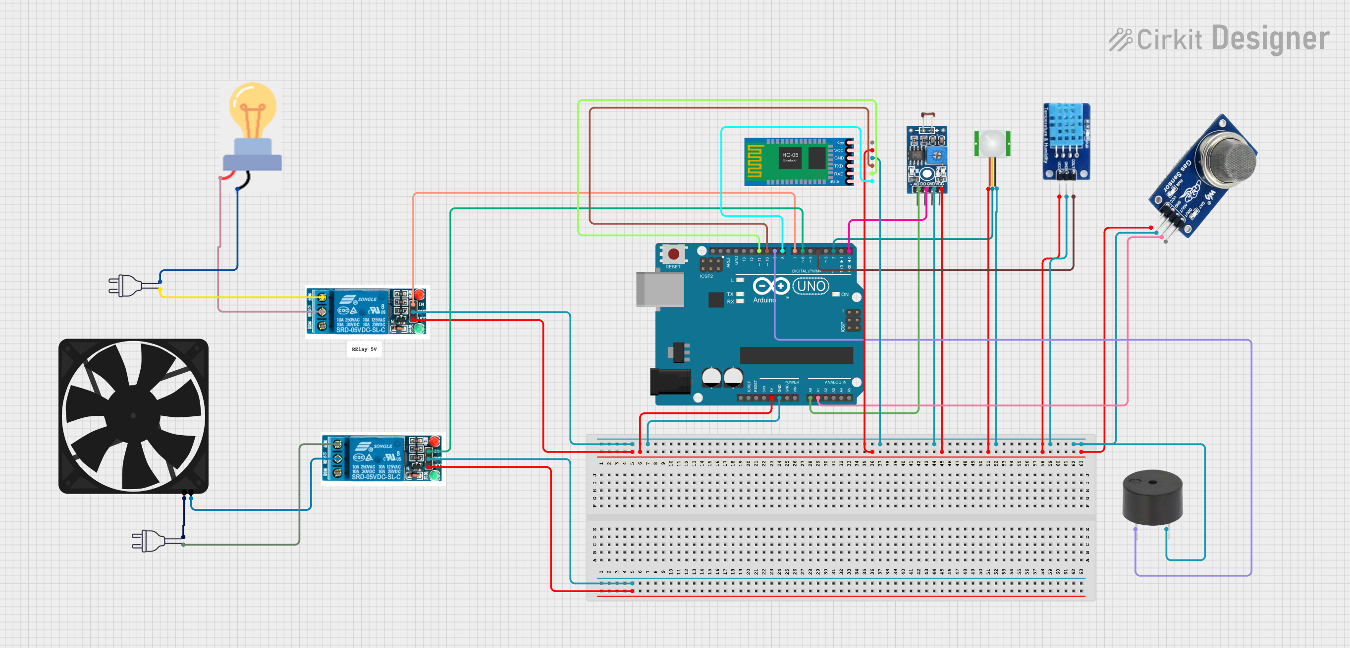
Explore Projects Built with Smart House Controller Board
Common Applications and Use Cases
- Home Automation: Control lighting, HVAC systems, and appliances.
- Security Systems: Integrate cameras, motion sensors, and alarms.
- Energy Management: Monitor and optimize energy usage.
- Remote Access: Manage devices via smartphone or web applications.
- Voice Control: Compatible with popular voice assistants like Alexa and Google Assistant.
Technical Specifications
The Smart House Controller Board is equipped with robust hardware and software capabilities to support a variety of smart home applications.
Key Technical Details
| Parameter | Specification |
|---|---|
| Operating Voltage | 5V DC |
| Power Consumption | 2W (typical) |
| Communication Protocols | Wi-Fi, Bluetooth, Zigbee, MQTT |
| Processor | 32-bit ARM Cortex-M4, 120 MHz |
| Memory | 512 KB Flash, 128 KB SRAM |
| GPIO Pins | 16 (configurable as digital/analog) |
| Operating Temperature | -20°C to 60°C |
| Dimensions | 85mm x 55mm x 15mm |
| User Interface | Web-based dashboard, mobile app support |
Pin Configuration and Descriptions
| Pin Number | Label | Description |
|---|---|---|
| 1 | VIN | Power input (5V DC) |
| 2 | GND | Ground |
| 3 | TX | UART Transmit |
| 4 | RX | UART Receive |
| 5 | GPIO1 | General-purpose I/O pin 1 |
| 6 | GPIO2 | General-purpose I/O pin 2 |
| 7 | GPIO3 | General-purpose I/O pin 3 |
| 8 | GPIO4 | General-purpose I/O pin 4 |
| 9 | SDA | I2C Data Line |
| 10 | SCL | I2C Clock Line |
| 11 | PWM1 | PWM Output 1 |
| 12 | PWM2 | PWM Output 2 |
| 13 | ADC1 | Analog-to-Digital Converter Input 1 |
| 14 | ADC2 | Analog-to-Digital Converter Input 2 |
| 15 | RESET | Reset Pin |
| 16 | INT | Interrupt Pin |
Usage Instructions
The Smart House Controller Board is designed for easy integration into smart home systems. Follow the steps below to get started:
How to Use the Component in a Circuit
- Power the Board: Connect a 5V DC power supply to the VIN and GND pins.
- Connect Devices: Attach sensors, actuators, or other peripherals to the GPIO, ADC, or PWM pins as required.
- Establish Communication: Use Wi-Fi, Bluetooth, or Zigbee to connect the board to your home network or other smart devices.
- Configure the System: Access the web-based dashboard or mobile app to configure automation rules, schedules, and device settings.
- Test the Setup: Verify that all connected devices respond correctly to commands and automation rules.
Important Considerations and Best Practices
- Power Supply: Ensure a stable 5V DC power source to avoid damage or malfunction.
- Network Security: Use strong passwords and encryption for Wi-Fi and other communication protocols to protect your smart home system.
- Firmware Updates: Regularly update the board's firmware to access new features and security patches.
- GPIO Usage: Avoid exceeding the maximum current rating (20mA per pin) to prevent damage.
- Environmental Conditions: Operate the board within the specified temperature range (-20°C to 60°C).
Example: Connecting to an Arduino UNO
The Smart House Controller Board can be interfaced with an Arduino UNO for additional functionality. Below is an example of how to send data from the Arduino to the board via UART.
// Example: Sending data from Arduino UNO to Smart House Controller Board
// Ensure TX (pin 1) of Arduino is connected to RX of the Controller Board
// Ensure RX (pin 0) of Arduino is connected to TX of the Controller Board

void setup() {
  Serial.begin(9600); // Initialize UART communication at 9600 baud rate
  delay(1000);        // Wait for the Controller Board to initialize
}

void loop() {
  Serial.println("Hello, Smart House Controller!");
  // Send a test message to the Controller Board
  delay(1000); // Wait 1 second before sending the next message
}
Troubleshooting and FAQs
Common Issues Users Might Face
- Board Not Powering On
- Solution: Verify the power supply voltage is 5V DC and connections to VIN and GND are secure.
- Devices Not Responding
- Solution: Check the connections to GPIO, ADC, or PWM pins. Ensure the devices are compatible with the board.
- Wi-Fi Connection Fails
- Solution: Ensure the correct SSID and password are entered. Check for interference or weak signal strength.
- Firmware Update Fails
- Solution: Ensure the board is connected to a stable power source and network during the update process.
Tips for Troubleshooting
- Use a multimeter to check voltage levels at the pins.
- Monitor the UART communication using a serial monitor to debug issues.
- Reset the board using the RESET pin if it becomes unresponsive.
FAQs
- Can I use the board with a 3.3V power supply?
- No, the board requires a 5V DC power supply for proper operation.
- Is the board compatible with Zigbee-based devices?
- Yes, the board supports Zigbee communication for device integration.
- How do I reset the board to factory settings?
- Press and hold the RESET pin for 10 seconds to restore factory settings.
By following this documentation, you can effectively integrate and utilize the Smart House Controller Board in your smart home projects.