How to Use LED matrix 8x8: Examples, Pinouts, and Specs
Introduction
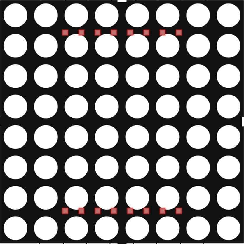
The LED Matrix 8x8 is a grid of 64 individual LEDs arranged in 8 rows and 8 columns. It is commonly used for displaying images, text, or patterns in a compact and visually appealing format. Each LED in the matrix can be individually controlled, allowing for dynamic and customizable displays. The component is widely used in applications such as digital signage, decorative lighting, gaming devices, and educational projects.
Explore Projects Built with LED matrix 8x8

Explore Projects Built with LED matrix 8x8
Technical Specifications
- Matrix Dimensions: 8 rows x 8 columns (64 LEDs total)
- LED Type: Standard or RGB (depending on the model)
- Operating Voltage: Typically 3.3V or 5V (check specific model)
- Current per LED: ~20mA (maximum)
- Control Method: Multiplexing (row and column addressing)
- Interface: Direct pin control or via driver ICs (e.g., MAX7219)
- Brightness Control: PWM (Pulse Width Modulation) or current-limiting resistors
Pin Configuration
The LED Matrix 8x8 typically has 16 pins, corresponding to the rows and columns of the matrix. The exact pinout may vary depending on the manufacturer, but a common configuration is as follows:
| Pin Number | Description | Function |
|---|---|---|
| 1 | Row 1 | Controls the first row of LEDs |
| 2 | Row 2 | Controls the second row of LEDs |
| 3 | Row 3 | Controls the third row of LEDs |
| 4 | Row 4 | Controls the fourth row of LEDs |
| 5 | Row 5 | Controls the fifth row of LEDs |
| 6 | Row 6 | Controls the sixth row of LEDs |
| 7 | Row 7 | Controls the seventh row of LEDs |
| 8 | Row 8 | Controls the eighth row of LEDs |
| 9 | Column 1 | Controls the first column of LEDs |
| 10 | Column 2 | Controls the second column of LEDs |
| 11 | Column 3 | Controls the third column of LEDs |
| 12 | Column 4 | Controls the fourth column of LEDs |
| 13 | Column 5 | Controls the fifth column of LEDs |
| 14 | Column 6 | Controls the sixth column of LEDs |
| 15 | Column 7 | Controls the seventh column of LEDs |
| 16 | Column 8 | Controls the eighth column of LEDs |
Note: Some LED matrices may include an integrated driver IC, which simplifies the pinout and control process.
Usage Instructions
How to Use the LED Matrix in a Circuit
- Power Supply: Connect the LED matrix to a 3.3V or 5V power source, depending on the model. Use current-limiting resistors to prevent damage to the LEDs.
- Control Method:
- For direct control, connect the rows and columns to GPIO pins on a microcontroller.
- For easier control, use a driver IC like the MAX7219, which reduces the number of required GPIO pins.
- Multiplexing: Activate one row at a time while controlling the columns to light up specific LEDs. This process is repeated rapidly to create the illusion of a steady image.
- Brightness Control: Use PWM signals or adjust the current-limiting resistors to control the brightness of the LEDs.
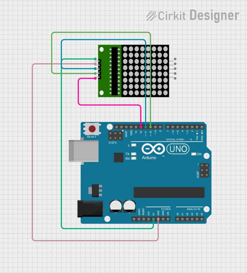
Example: Connecting to an Arduino UNO
The following example demonstrates how to use an 8x8 LED matrix with a MAX7219 driver IC and an Arduino UNO.
Circuit Connections
- Connect the VCC and GND pins of the MAX7219 to the 5V and GND pins of the Arduino.
- Connect the DIN, CS, and CLK pins of the MAX7219 to Arduino pins 11, 10, and 13, respectively.
- Connect the LED matrix to the MAX7219 as per the manufacturer's instructions.
Arduino Code
#include <LedControl.h>
// Include the LedControl library for MAX7219 control

// Create a LedControl object (DIN=11, CLK=13, CS=10, 1 device)
LedControl lc = LedControl(11, 13, 10, 1);

void setup() {
  lc.shutdown(0, false); // Wake up the MAX7219
  lc.setIntensity(0, 8); // Set brightness level (0-15)
  lc.clearDisplay(0);    // Clear the display
}

void loop() {
  // Display a simple pattern (diagonal line)
  for (int i = 0; i < 8; i++) {
    lc.setLed(0, i, i, true); // Turn on LED at row i, column i
    delay(200);               // Wait for 200ms
  }
  delay(1000);                // Pause for 1 second
  lc.clearDisplay(0);         // Clear the display
}
Note: Install the
LedControllibrary in the Arduino IDE before uploading the code.
Important Considerations
- Current Limiting: Always use resistors or a driver IC to limit the current through the LEDs.
- Refresh Rate: Ensure a high refresh rate during multiplexing to avoid flickering.
- Heat Management: Prolonged use at high brightness may generate heat; ensure proper ventilation.
Troubleshooting and FAQs
Common Issues
LEDs Not Lighting Up:
- Check the power supply and ensure correct voltage.
- Verify all connections, especially the row and column pins.
- If using a driver IC, ensure it is properly connected and configured.
Flickering LEDs:
- Increase the refresh rate during multiplexing.
- Check for loose connections or insufficient power supply.
Dim LEDs:
- Verify the current-limiting resistors are appropriate for the LEDs.
- Ensure the power supply can provide sufficient current.
Incorrect Patterns:
- Double-check the wiring of rows and columns.
- Verify the code logic for addressing the LEDs.
FAQs
Can I use an LED matrix without a driver IC? Yes, but it requires more GPIO pins and complex multiplexing logic.
What is the maximum brightness I can achieve? The brightness depends on the current through each LED. Do not exceed the maximum current rating (typically 20mA per LED).
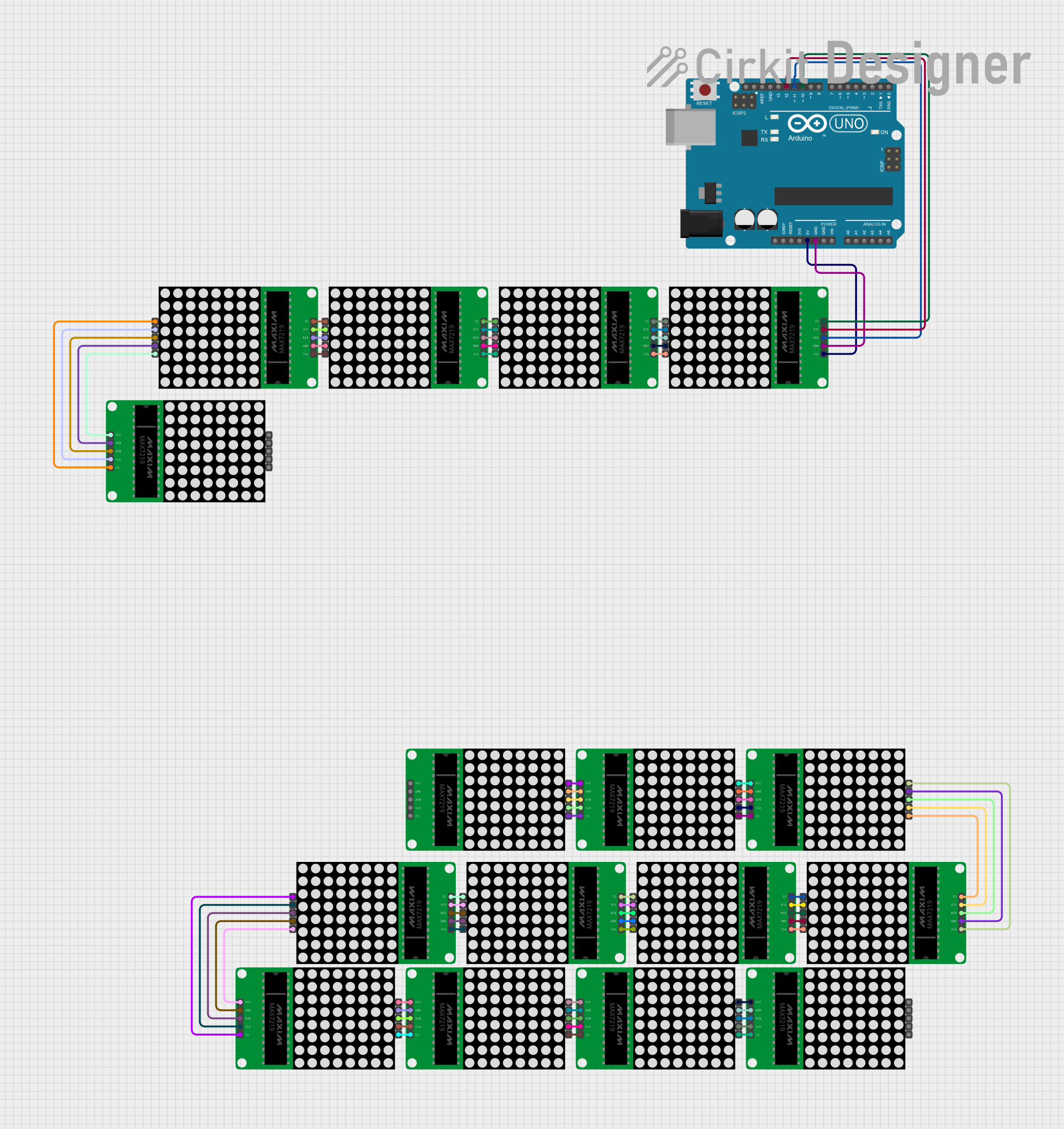
Can I daisy-chain multiple LED matrices? Yes, if using a driver IC like the MAX7219, you can chain multiple matrices for larger displays.
How do I display custom patterns or text? Use an array to define the on/off state of each LED and update the matrix accordingly in your code. Libraries like
LedControlsimplify this process.
By following this documentation, you can effectively integrate and use an 8x8 LED matrix in your projects!