How to Use ESP32: Examples, Pinouts, and Specs
Introduction
The ESP32, manufactured by THINGS KIT MINI with the part ID NODEMCU, is a low-cost, low-power system on a chip (SoC) designed for IoT applications. It integrates Wi-Fi and Bluetooth capabilities, making it a versatile and powerful solution for a wide range of projects. The ESP32 is widely used in smart home devices, wearable electronics, industrial automation, and other applications requiring wireless connectivity and efficient processing.
Explore Projects Built with ESP32


Explore Projects Built with ESP32
Common Applications and Use Cases
- IoT Devices: Smart home automation, environmental monitoring, and connected appliances.
- Wearables: Fitness trackers, smartwatches, and health monitoring devices.
- Industrial Automation: Wireless sensor networks and machine-to-machine communication.
- Prototyping and Development: Ideal for hobbyists and engineers building connected systems.
- Robotics: Remote-controlled robots and drones with wireless communication.
Technical Specifications
The ESP32 is a feature-rich SoC with the following key specifications:
Key Technical Details
- Processor: Dual-core Xtensa® 32-bit LX6 microprocessor, up to 240 MHz.
- Memory: 520 KB SRAM, 4 MB Flash (varies by model).
- Wireless Connectivity:
- Wi-Fi: 802.11 b/g/n (2.4 GHz).
- Bluetooth: v4.2 BR/EDR and BLE.
- Operating Voltage: 3.3V.
- GPIO Pins: 34 programmable GPIOs.
- ADC Channels: 18 (12-bit resolution).
- DAC Channels: 2 (8-bit resolution).
- Communication Interfaces: UART, SPI, I2C, I2S, CAN, PWM.
- Power Consumption: Ultra-low power consumption in deep sleep mode (~10 µA).
- Operating Temperature: -40°C to 125°C.
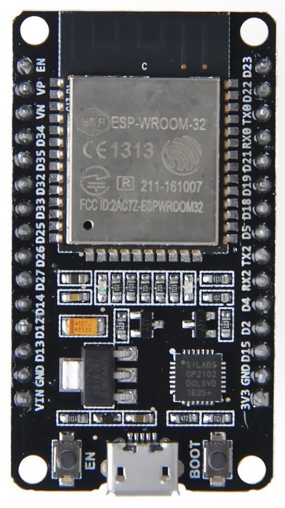
Pin Configuration and Descriptions
The ESP32 NODEMCU board has a standard pinout. Below is a table of the most commonly used pins:
| Pin Name | Function | Description |
|---|---|---|
| VIN | Power Input | Input voltage (5V) for powering the board. |
| 3V3 | Power Output | Regulated 3.3V output for external components. |
| GND | Ground | Ground connection. |
| EN | Enable | Enables or disables the chip. Active high. |
| GPIO0 | General Purpose I/O | Can be used for input, output, or boot mode selection. |
| GPIO2 | General Purpose I/O | Default boot mode pin. |
| GPIO12-19 | General Purpose I/O | Configurable for digital I/O, ADC, or other functions. |
| TXD0, RXD0 | UART Communication | Default UART pins for serial communication. |
| ADC1_CH0-7 | Analog Input | 12-bit ADC channels for analog-to-digital conversion. |
| DAC1, DAC2 | Digital-to-Analog Converter | 8-bit DAC channels for analog output. |
| SCL, SDA | I2C Communication | Clock and data lines for I2C communication. |
| SPI Pins | SPI Communication | Includes MOSI, MISO, SCK, and CS for SPI communication. |
| BOOT | Boot Mode Selection | Used to enter bootloader mode for flashing firmware. |
Usage Instructions
How to Use the ESP32 in a Circuit
- Powering the ESP32: Connect the VIN pin to a 5V power source or use the micro-USB port for power and programming.
- Connecting Peripherals: Use the GPIO pins for digital I/O, ADC pins for analog input, and DAC pins for analog output.
- Programming the ESP32: Use the Arduino IDE or ESP-IDF (Espressif IoT Development Framework) to write and upload code.
- Wi-Fi and Bluetooth Setup: Configure the Wi-Fi and Bluetooth modules in your code to enable wireless communication.
Important Considerations and Best Practices
- Voltage Levels: Ensure all connected components operate at 3.3V logic levels to avoid damaging the ESP32.
- Power Supply: Use a stable power source to prevent unexpected resets or instability.
- Pin Multiplexing: Many pins have multiple functions; consult the datasheet to avoid conflicts.
- Deep Sleep Mode: Use deep sleep mode to conserve power in battery-powered applications.
- Firmware Updates: Keep the firmware updated to benefit from the latest features and bug fixes.
Example Code for Arduino UNO Integration
Below is an example of how to use the ESP32 with the Arduino IDE to connect to a Wi-Fi network:
#include <WiFi.h> // Include the Wi-Fi library for ESP32

const char* ssid = "Your_SSID";       // Replace with your Wi-Fi network name
const char* password = "Your_Password"; // Replace with your Wi-Fi password

void setup() {
  Serial.begin(115200); // Initialize serial communication at 115200 baud
  delay(1000);          // Wait for a second to stabilize the serial monitor

  Serial.println("Connecting to Wi-Fi...");
  WiFi.begin(ssid, password); // Start connecting to the Wi-Fi network

  while (WiFi.status() != WL_CONNECTED) {
    delay(500); // Wait for connection
    Serial.print(".");
  }

  Serial.println("\nWi-Fi connected!");
  Serial.print("IP Address: ");
  Serial.println(WiFi.localIP()); // Print the assigned IP address
}

void loop() {
  // Add your main code here
}
Troubleshooting and FAQs
Common Issues and Solutions
- ESP32 Not Connecting to Wi-Fi:
- Solution: Double-check the SSID and password in your code. Ensure the Wi-Fi network is active and within range.
- Board Not Detected by Computer:
- Solution: Install the correct USB-to-serial driver for the ESP32 NODEMCU board.
- Random Resets or Instability:
- Solution: Use a stable power supply and avoid overloading the GPIO pins.
- Upload Errors in Arduino IDE:
- Solution: Ensure the correct board and COM port are selected in the Arduino IDE. Press and hold the BOOT button during upload if needed.
FAQs
- Q: Can the ESP32 operate on battery power?
- A: Yes, the ESP32 can be powered by a battery. Use deep sleep mode to extend battery life.
- Q: How do I reset the ESP32?
- A: Press the RESET button on the board to restart the ESP32.
- Q: Can I use the ESP32 with sensors and actuators?
- A: Yes, the ESP32 supports a wide range of sensors and actuators via its GPIO, ADC, and communication interfaces.
This documentation provides a comprehensive guide to using the ESP32 NODEMCU board effectively in your projects.