How to Use MQ 135: Examples, Pinouts, and Specs
Introduction
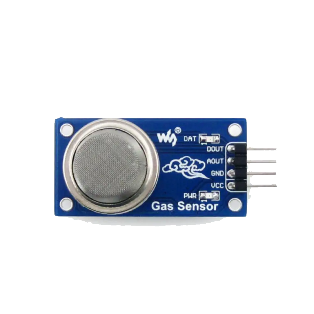
The MQ-135 is a versatile gas sensor designed to detect a wide range of gases, including ammonia, nitrogen, oxygen, alcohols, aromatic compounds, sulfide, and smoke. It is widely used in air quality monitoring systems, industrial applications, and safety systems to ensure a healthy and safe environment. The sensor provides an analog output that can be easily interfaced with microcontrollers like the Arduino UNO for real-time monitoring and data logging.
Explore Projects Built with MQ 135
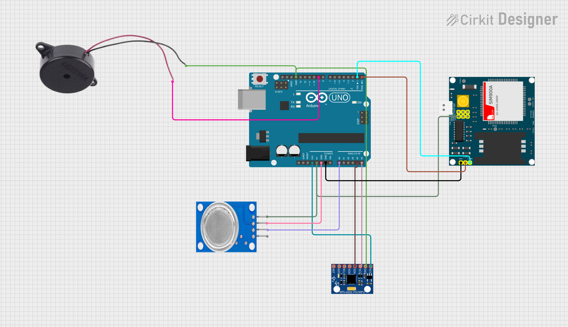
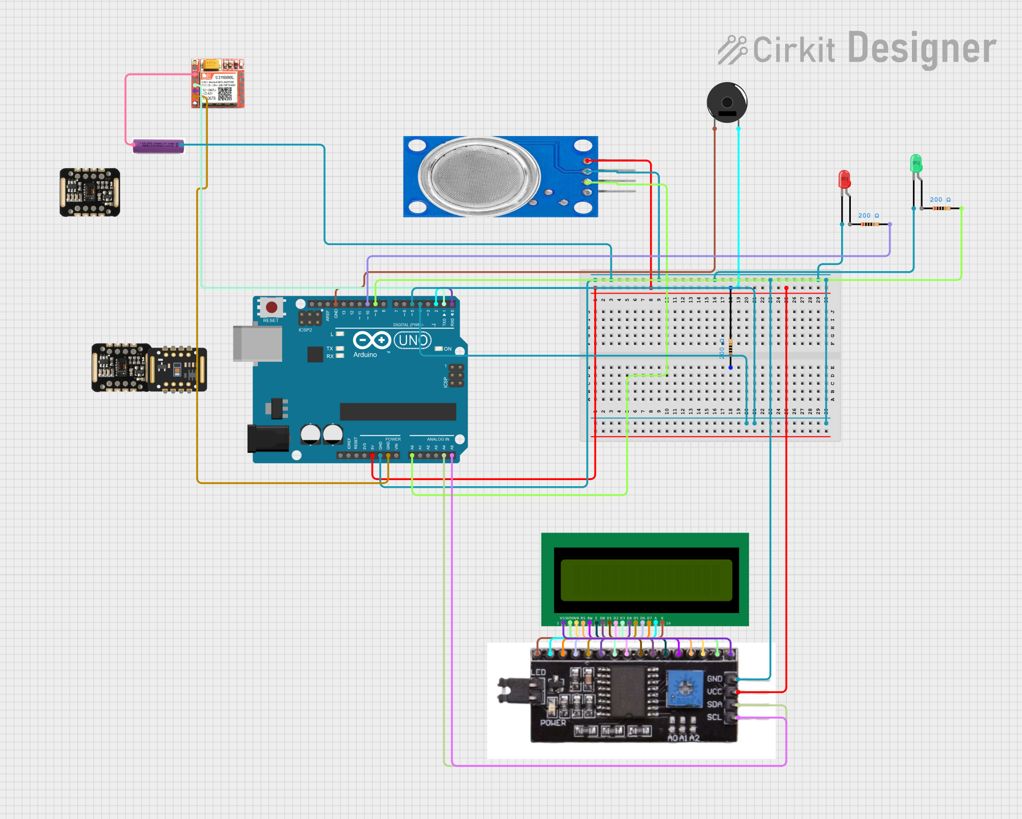
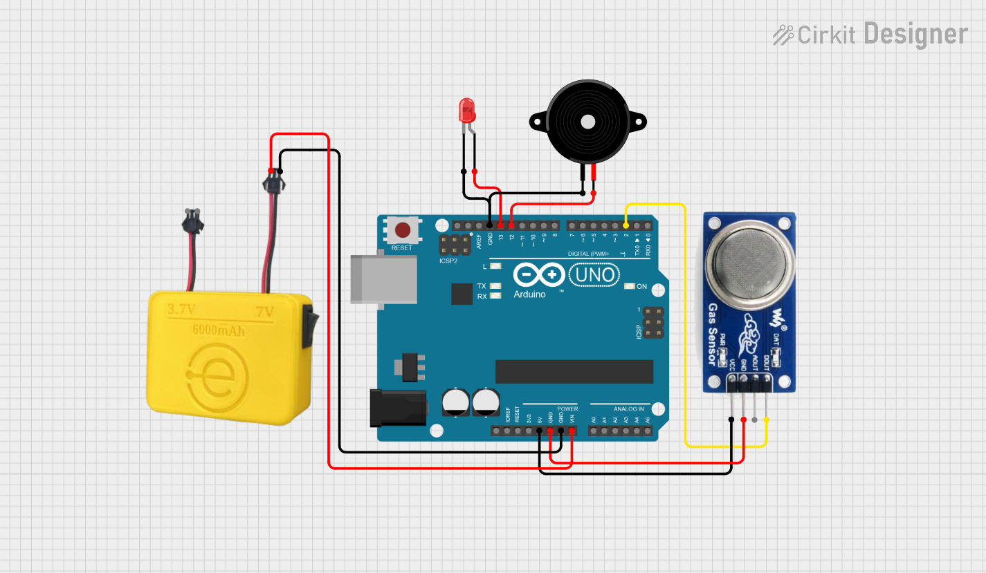
Explore Projects Built with MQ 135
Technical Specifications
Key Technical Details
| Parameter | Value |
|---|---|
| Operating Voltage | 5V DC |
| Load Resistance | 20kΩ (typical) |
| Heating Resistance | 33Ω ± 5% |
| Heating Power | ≤ 800mW |
| Sensing Resistance | 10kΩ - 60kΩ (in clean air) |
| Detection Range | 10 - 1000 ppm (NH3, NOx, etc.) |
| Preheat Time | ≥ 24 hours |
| Response Time | ≤ 10 seconds |
| Recovery Time | ≤ 30 seconds |
| Operating Temperature | -20°C to 50°C |
| Humidity Range | 20% - 90% RH |
Pin Configuration and Descriptions
| Pin No. | Pin Name | Description |
|---|---|---|
| 1 | VCC | Power supply (5V DC) |
| 2 | GND | Ground |
| 3 | AOUT | Analog output voltage proportional to gas concentration |
| 4 | DOUT | Digital output (threshold-based) |
Usage Instructions
How to Use the Component in a Circuit
- Power Supply: Connect the VCC pin to a 5V DC power supply and the GND pin to the ground.
- Analog Output: Connect the AOUT pin to an analog input pin on your microcontroller (e.g., A0 on Arduino UNO).
- Digital Output: Optionally, connect the DOUT pin to a digital input pin on your microcontroller if you want to use the threshold-based digital output.
Important Considerations and Best Practices
- Preheat Time: The sensor requires a preheat time of at least 24 hours for optimal performance. Ensure the sensor is powered on for this duration before taking any measurements.
- Calibration: Calibrate the sensor in a clean air environment to establish a baseline reading. This helps in accurately detecting gas concentrations.
- Ventilation: Ensure proper ventilation around the sensor to avoid saturation and ensure accurate readings.
- Avoid Contaminants: Keep the sensor away from water, oil, and other contaminants that could affect its performance.
Sample Arduino Code
// MQ-135 Gas Sensor - Arduino UNO Example Code

const int analogPin = A0; // Analog input pin connected to AOUT
const int digitalPin = 2; // Digital input pin connected to DOUT (optional)
int sensorValue = 0;      // Variable to store the analog value

void setup() {
  Serial.begin(9600);     // Initialize serial communication at 9600 bps
  pinMode(digitalPin, INPUT); // Set digital pin as input (optional)
}

void loop() {
  sensorValue = analogRead(analogPin); // Read the analog value from the sensor
  Serial.print("Analog Value: ");
  Serial.println(sensorValue); // Print the analog value to the serial monitor

  // Optional: Read the digital output
  int digitalValue = digitalRead(digitalPin);
  Serial.print("Digital Value: ");
  Serial.println(digitalValue); // Print the digital value to the serial monitor

  delay(1000); // Wait for 1 second before taking the next reading
}
Troubleshooting and FAQs
Common Issues Users Might Face
No Output or Incorrect Readings:
- Solution: Ensure the sensor is properly connected to the power supply and ground. Check for loose connections and ensure the preheat time is met.
Fluctuating Readings:
- Solution: Ensure the sensor is in a stable environment with consistent airflow. Avoid placing the sensor near sources of interference or contaminants.
Slow Response Time:
- Solution: Verify that the sensor is not saturated with high concentrations of gas. Allow the sensor to recover in clean air if necessary.
FAQs
How long does the sensor last?
- The MQ-135 sensor has a lifespan of approximately 2 years under normal operating conditions.
Can the sensor detect multiple gases simultaneously?
- Yes, the sensor can detect a range of gases, but it provides a combined output. Specific gas concentration detection requires calibration and additional processing.
Is the sensor waterproof?
- No, the MQ-135 sensor is not waterproof. Avoid exposure to water and other liquids.
By following this documentation, users can effectively integrate the MQ-135 gas sensor into their projects, ensuring accurate and reliable gas detection for various applications.