How to Use DC DC CONVERTER UP LCD: Examples, Pinouts, and Specs
Introduction
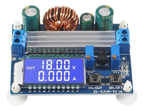
The BEGGLE DC DC CONVERTER UP LCD (Part ID: 1) is a versatile step-up voltage regulator designed to efficiently convert lower DC input voltages to higher DC output voltages. Equipped with an integrated LCD display, this component provides real-time monitoring of input voltage, output voltage, and current, making it ideal for applications requiring precise voltage regulation and monitoring.
Common applications include:
- Powering devices requiring higher voltage from a lower voltage source (e.g., 5V to 12V).
- Battery-powered systems where voltage boosting is necessary.
- DIY electronics projects and prototyping.
- Renewable energy systems, such as solar-powered setups.
Explore Projects Built with DC DC CONVERTER UP LCD
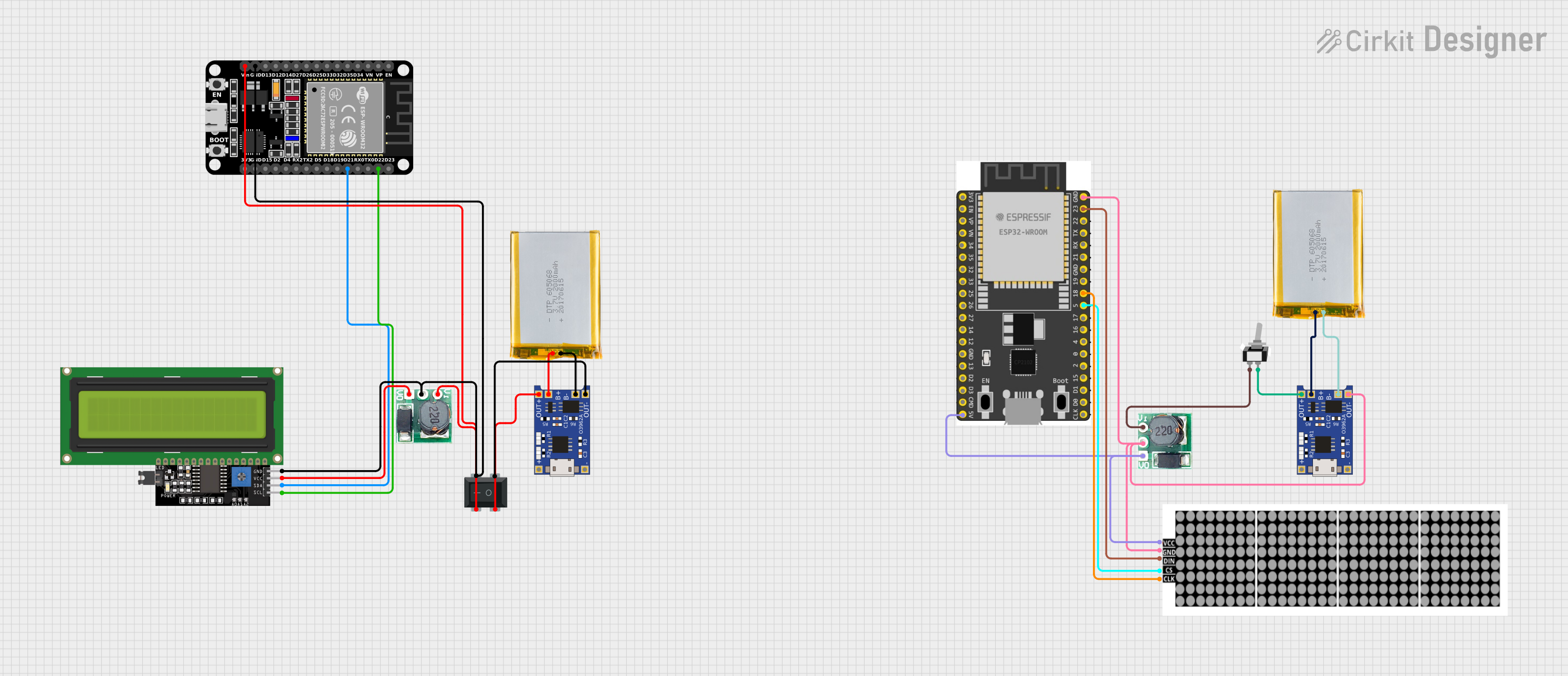
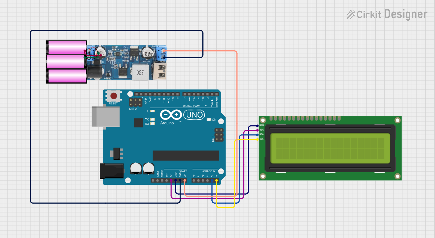
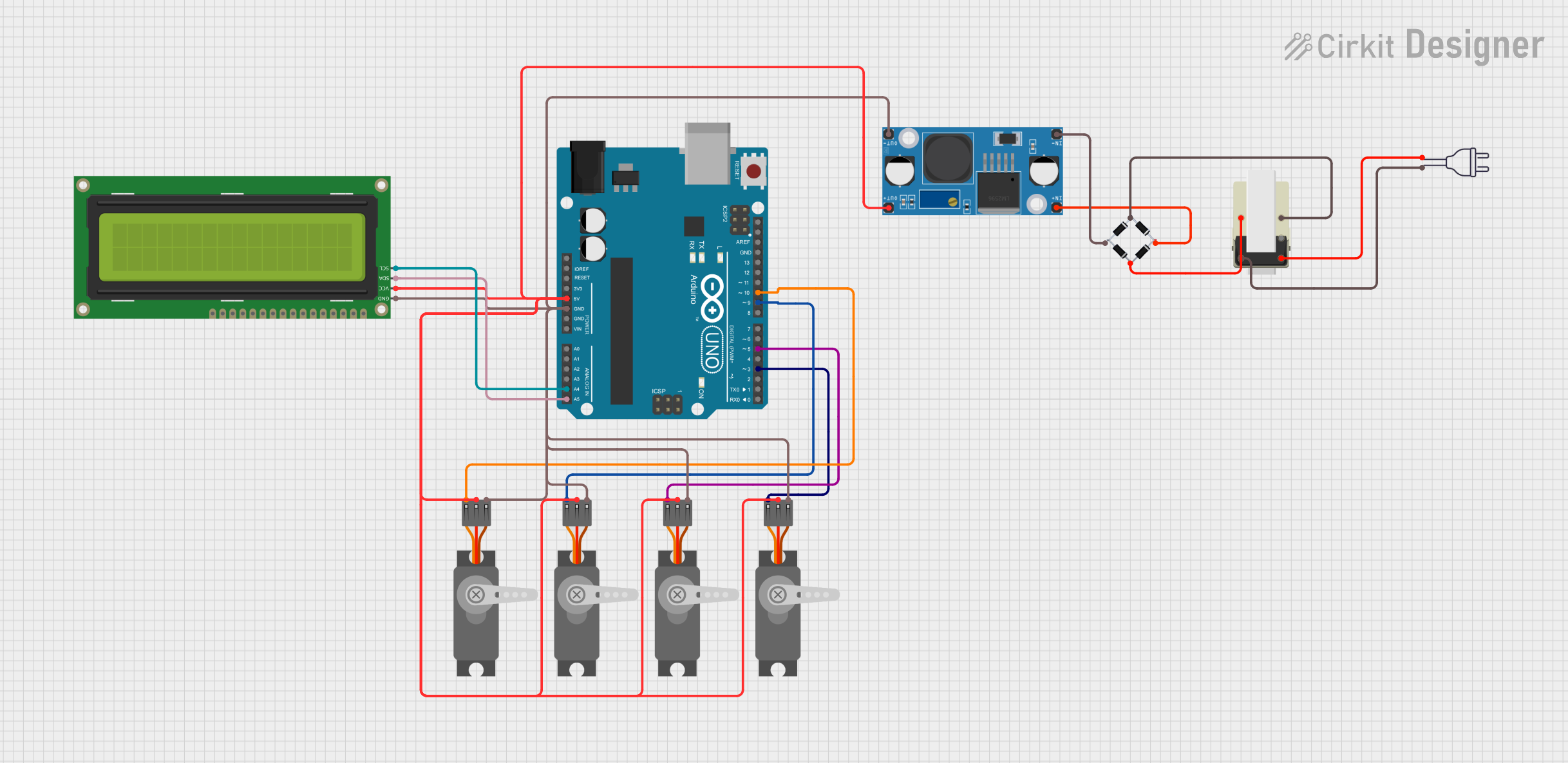
Explore Projects Built with DC DC CONVERTER UP LCD
Technical Specifications
Key Technical Details
- Input Voltage Range: 3V to 35V DC
- Output Voltage Range: 5V to 55V DC (adjustable)
- Maximum Output Current: 5A (with proper heat dissipation)
- Efficiency: Up to 96% (depending on input/output conditions)
- LCD Display: Real-time input voltage, output voltage, and current readings
- Operating Temperature: -40°C to +85°C
- Dimensions: 60mm x 30mm x 20mm
- Weight: 25g
Pin Configuration and Descriptions
The DC DC CONVERTER UP LCD has the following pin layout:
| Pin Name | Description |
|---|---|
| VIN+ | Positive input voltage terminal (connect to the positive side of the power source). |
| VIN- | Negative input voltage terminal (connect to the ground of the power source). |
| VOUT+ | Positive output voltage terminal (connect to the positive side of the load). |
| VOUT- | Negative output voltage terminal (connect to the ground of the load). |
| ADJ | Voltage adjustment potentiometer (rotate to set the desired output voltage). |
Usage Instructions
How to Use the Component in a Circuit
Connect the Input Voltage:
- Attach the positive terminal of your DC power source to the
VIN+pin. - Attach the ground terminal of your DC power source to the
VIN-pin.
- Attach the positive terminal of your DC power source to the
Connect the Output Load:
- Connect the positive terminal of your load to the
VOUT+pin. - Connect the ground terminal of your load to the
VOUT-pin.
- Connect the positive terminal of your load to the
Adjust the Output Voltage:
- Use the
ADJpotentiometer to set the desired output voltage. Turn clockwise to increase the voltage and counterclockwise to decrease it. - Monitor the LCD display to verify the output voltage.
- Use the
Power On:
- Once all connections are secure, power on the input source. The LCD will display the input voltage, output voltage, and current in real time.
Important Considerations and Best Practices
- Ensure the input voltage is within the specified range (3V to 35V DC).
- Do not exceed the maximum output current of 5A. Use a heatsink or active cooling for high-current applications.
- Always verify the output voltage with a multimeter before connecting sensitive devices.
- Avoid short circuits between the input and output terminals.
- For Arduino or microcontroller projects, ensure the output voltage matches the required operating voltage of the board.
Example: Using with Arduino UNO
To power an Arduino UNO with 9V from a 5V power source:
- Connect the 5V power source to
VIN+andVIN-. - Adjust the output voltage to 9V using the
ADJpotentiometer. - Connect
VOUT+to the Arduino's VIN pin andVOUT-to the Arduino's GND pin.
Here is an example Arduino code to read the input voltage using an analog pin:
// Example code to read input voltage using Arduino UNO
const int analogPin = A0; // Connect the input voltage to analog pin A0
float inputVoltage = 0.0;

void setup() {
  Serial.begin(9600); // Initialize serial communication at 9600 baud
}

void loop() {
  int sensorValue = analogRead(analogPin); // Read the analog input
  inputVoltage = sensorValue * (5.0 / 1023.0); // Convert to voltage (assuming 5V reference)

  // Print the input voltage to the Serial Monitor
  Serial.print("Input Voltage: ");
  Serial.print(inputVoltage);
  Serial.println(" V");

  delay(1000); // Wait for 1 second before the next reading
}
Troubleshooting and FAQs
Common Issues and Solutions
No Output Voltage:
- Verify that the input voltage is within the specified range.
- Check all connections for proper polarity and secure contact.
- Ensure the
ADJpotentiometer is not set to the minimum output voltage.
Overheating:
- Ensure the load current does not exceed 5A.
- Use a heatsink or active cooling for high-power applications.
LCD Display Not Working:
- Check the input voltage; the LCD requires a minimum input voltage to operate.
- Inspect the module for physical damage or loose connections.
Output Voltage Fluctuations:
- Verify that the input power source is stable and capable of supplying sufficient current.
- Avoid using excessively long or thin wires for connections.
FAQs
Q1: Can this module step down voltage as well?
A1: No, this is a step-up (boost) converter and cannot step down voltage. Use a buck converter for step-down applications.
Q2: Is the output voltage adjustable while the module is powered?
A2: Yes, the output voltage can be adjusted in real time using the ADJ potentiometer.
Q3: Can I use this module with a battery as the input source?
A3: Yes, it is compatible with battery-powered systems. Ensure the battery voltage is within the input range.
Q4: What happens if the input voltage exceeds 35V?
A4: Exceeding the input voltage range may damage the module. Always stay within the specified limits.
By following this documentation, you can effectively integrate the BEGGLE DC DC CONVERTER UP LCD into your projects and ensure reliable performance.