
How to Use usb c male : Examples, Pinouts, and Specs
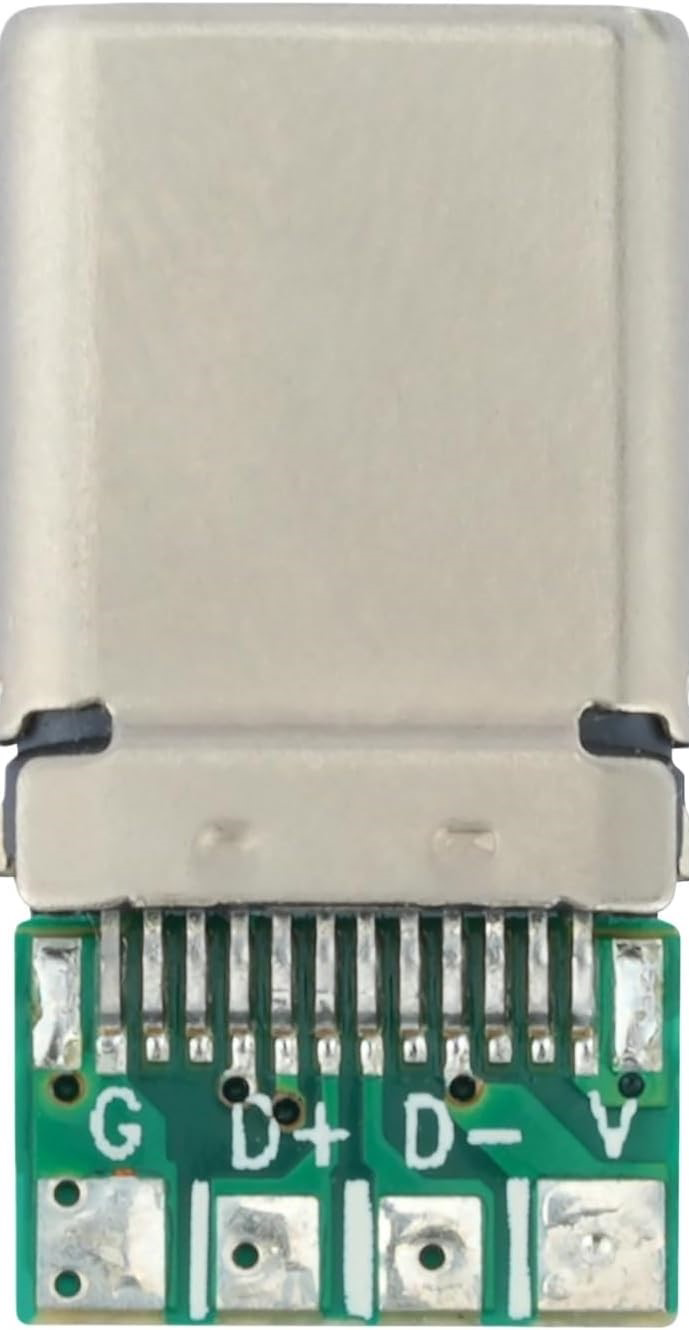
 Design with usb c male in Cirkit Designer
Introduction
The USB Type-C male connector is a versatile and compact interface designed for data transfer and power delivery. Its reversible design eliminates the frustration of incorrect orientation during connection, making it user-friendly and efficient. This connector supports high-speed data transfer, video output, and power delivery, making it a popular choice for modern electronic devices.
Explore Projects Built with usb c male
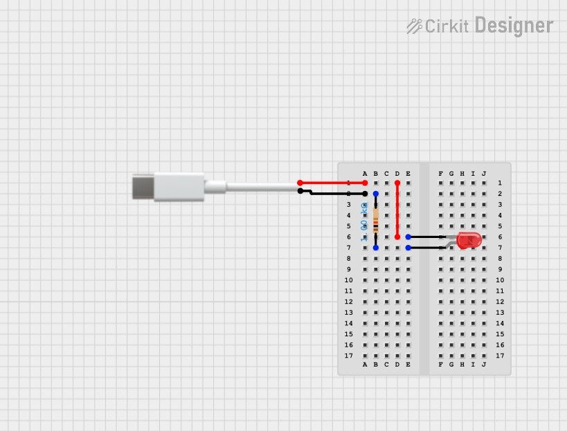 Open Project in Cirkit Designer
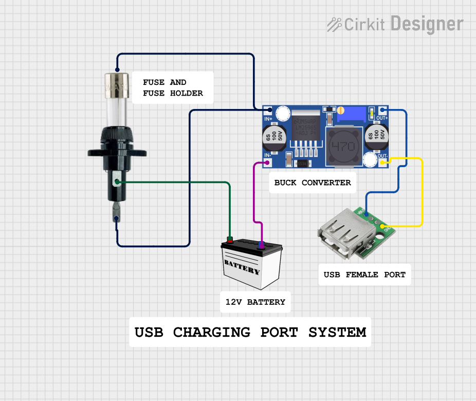 Open Project in Cirkit Designer
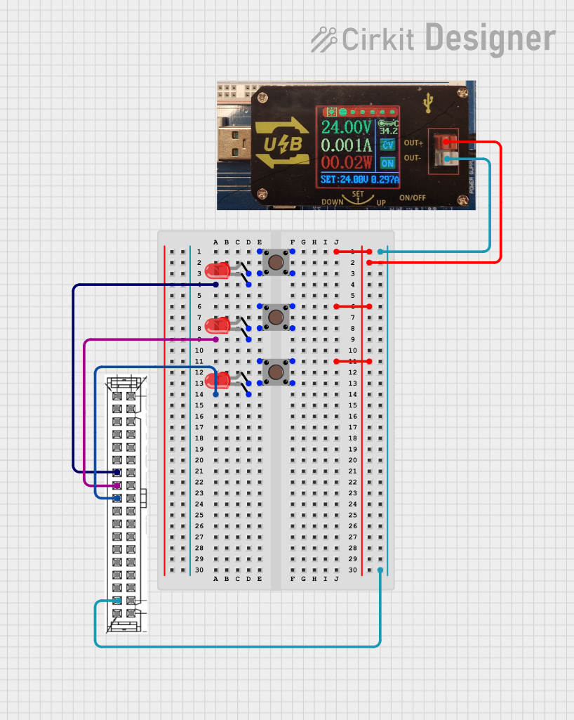 Open Project in Cirkit Designer
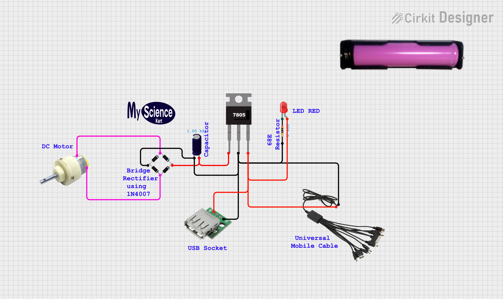 Open Project in Cirkit Designer
Explore Projects Built with usb c male
Open Project in Cirkit DesignerOpen Project in Cirkit DesignerOpen Project in Cirkit DesignerOpen Project in Cirkit DesignerCommon Applications and Use Cases
- Charging and powering devices such as smartphones, laptops, and tablets
- High-speed data transfer between devices
- Video output for monitors and displays (e.g., USB-C to HDMI)
- Integration in embedded systems and development boards
- Use in USB-C hubs and docking stations
Technical Specifications
The USB Type-C male connector adheres to the USB 3.1/3.2 and USB Power Delivery (USB-PD) standards, offering robust performance for a wide range of applications.
Key Technical Details
| Parameter | Specification |
|---|---|
| Connector Type | USB Type-C Male |
| Data Transfer Rate | Up to 10 Gbps (USB 3.1 Gen 2) |
| Power Delivery | Up to 100W (20V, 5A) |
| Reversibility | Yes |
| Number of Pins | 24 |
| Operating Temperature | -25°C to 85°C |
| Durability | 10,000+ insertion/removal cycles |
Pin Configuration and Descriptions
The USB Type-C male connector features 24 pins, which are symmetrically arranged to support its reversible design. Below is a simplified pinout table:
| Pin Number | Name | Description |
|---|---|---|
| A1, B1 | GND | Ground |
| A4, B4 | VBUS | Power supply (up to 20V, 5A) |
| A5, B5 | CC1, CC2 | Configuration channel for orientation and power delivery |
| A6, B6 | D+ | USB 2.0 differential pair (positive) |
| A7, B7 | D- | USB 2.0 differential pair (negative) |
| A8, B8 | SBU1, SBU2 | Sideband use |
| A9, B9 | TX+ | USB 3.x differential pair (positive) |
| A10, B10 | TX- | USB 3.x differential pair (negative) |
| A11, B11 | RX+ | USB 3.x differential pair (positive) |
| A12, B12 | RX- | USB 3.x differential pair (negative) |
Usage Instructions
How to Use the USB Type-C Male Connector in a Circuit
- Soldering: Ensure proper alignment of the connector's pins with the PCB pads. Use a fine-tipped soldering iron and apply minimal heat to avoid damaging the connector.
- Power Delivery: If using USB-PD, connect the CC1 and CC2 pins to a USB-PD controller IC to negotiate power delivery profiles.
- Data Transfer: Connect the D+/D- pins for USB 2.0 communication or the TX+/TX-, RX+/RX- pairs for USB 3.x communication.
- Reversibility: Design the circuit to handle both orientations by connecting symmetrical pins (e.g., A1 to B1 for GND).
Important Considerations and Best Practices
- Voltage and Current Ratings: Ensure the connected devices and cables support the required voltage and current levels.
- Heat Management: For high-power applications, consider thermal management solutions to prevent overheating.
- Cable Quality: Use certified USB-C cables to ensure reliable performance and safety.
- Signal Integrity: Keep high-speed signal traces (e.g., TX/RX pairs) short and impedance-matched to minimize signal loss.
Example: Connecting USB Type-C to an Arduino UNO
While the Arduino UNO does not natively support USB Type-C, you can use a USB-C breakout board to interface with it. Below is an example of using the USB-C connector for power input:
// Example: Using USB-C to power an Arduino UNO
// Connect the VBUS pin of the USB-C breakout board to the Arduino's VIN pin.
// Connect the GND pin of the USB-C breakout board to the Arduino's GND pin.

void setup() {
  // No specific setup required for power input
}

void loop() {
  // Your main code here
}
Troubleshooting and FAQs
Common Issues
No Power Delivery:
- Cause: Incorrect connection of CC1/CC2 pins or incompatible cable.
- Solution: Verify the CC1/CC2 connections and use a certified USB-C cable.
Data Transfer Fails:
- Cause: Misaligned or damaged TX/RX or D+/D- connections.
- Solution: Check solder joints and ensure proper alignment of pins.
Overheating:
- Cause: Excessive current draw or poor thermal management.
- Solution: Ensure the current does not exceed 5A and implement heat dissipation measures.
FAQs
Q: Can I use the USB Type-C male connector for video output?
A: Yes, the USB Type-C connector supports Alternate Modes (e.g., DisplayPort) for video output, but this requires a compatible device and cable.
Q: Is the USB Type-C male connector backward compatible with USB 2.0?
A: Yes, the connector supports USB 2.0 through the D+/D- pins.
Q: How do I ensure proper orientation handling in my circuit?
A: Connect symmetrical pins (e.g., A1 to B1 for GND) to ensure functionality regardless of orientation.