Cirkit Designer Logo
Cirkit Designer
Your all-in-one circuit design IDE
Home / 
Component Documentation

How to Use 4023: Examples, Pinouts, and Specs

Image of 4023
Cirkit Designer LogoDesign with 4023 in Cirkit Designer

Introduction

The 4023 is a dual 4-input NAND gate integrated circuit (IC) that is widely used in digital electronics for implementing various logic functions. This component features two independent NAND gates, each capable of accepting four inputs, making it a versatile choice for compact logic design. The 4023 is commonly utilized in applications such as combinational logic circuits, data processing, and control systems.

Explore Projects Built with 4023

Use Cirkit Designer to design, explore, and prototype these projects online. Some projects support real-time simulation. Click "Open Project" to start designing instantly!
Logic Gate Circuit with 7408 AND and 7432 OR ICs
Image of gate: A project utilizing 4023 in a practical application
This circuit includes a 7408 AND gate IC and a 7432 OR gate IC, both powered by a common VCC and GND connection. The circuit is designed to perform basic logical operations, combining AND and OR gates for digital signal processing.
Cirkit Designer LogoOpen Project in Cirkit Designer
Arduino Nano 33 BLE Battery-Powered Display Interface
Image of senior design 1: A project utilizing 4023 in a practical application
This circuit features a Nano 33 BLE microcontroller interfaced with a TM1637 4-digit 7-segment display for information output, powered by a 3.7V battery managed by a TP4056 charging module. The microcontroller communicates with the display to present data, while the TP4056 ensures the battery is charged safely and provides power to the system.
Cirkit Designer LogoOpen Project in Cirkit Designer
Pushbutton-Controlled Interface with 40-Pin Connector and UBS Power Supply
Image of connect 4: A project utilizing 4023 in a practical application
This circuit consists of a 40-pin connector interfacing with four pushbuttons and a UBS power supply. The pushbuttons are used as inputs to the connector, which then relays the signals to other components or systems. The UBS power supply provides the necessary 24V power to the pushbuttons and the common ground for the circuit.
Cirkit Designer LogoOpen Project in Cirkit Designer
ESP32-Based Battery-Powered Multi-Sensor System
Image of Dive sense: A project utilizing 4023 in a practical application
This circuit consists of a TP4056 module connected to a 3.7V LiPo battery, providing a charging interface for the battery. The TP4056 manages the charging process by connecting its B+ and B- pins to the battery's positive and ground terminals, respectively.
Cirkit Designer LogoOpen Project in Cirkit Designer

Explore Projects Built with 4023

Use Cirkit Designer to design, explore, and prototype these projects online. Some projects support real-time simulation. Click "Open Project" to start designing instantly!
Image of gate: A project utilizing 4023 in a practical application
Logic Gate Circuit with 7408 AND and 7432 OR ICs
This circuit includes a 7408 AND gate IC and a 7432 OR gate IC, both powered by a common VCC and GND connection. The circuit is designed to perform basic logical operations, combining AND and OR gates for digital signal processing.
Cirkit Designer LogoOpen Project in Cirkit Designer
Image of senior design 1: A project utilizing 4023 in a practical application
Arduino Nano 33 BLE Battery-Powered Display Interface
This circuit features a Nano 33 BLE microcontroller interfaced with a TM1637 4-digit 7-segment display for information output, powered by a 3.7V battery managed by a TP4056 charging module. The microcontroller communicates with the display to present data, while the TP4056 ensures the battery is charged safely and provides power to the system.
Cirkit Designer LogoOpen Project in Cirkit Designer
Image of connect 4: A project utilizing 4023 in a practical application
Pushbutton-Controlled Interface with 40-Pin Connector and UBS Power Supply
This circuit consists of a 40-pin connector interfacing with four pushbuttons and a UBS power supply. The pushbuttons are used as inputs to the connector, which then relays the signals to other components or systems. The UBS power supply provides the necessary 24V power to the pushbuttons and the common ground for the circuit.
Cirkit Designer LogoOpen Project in Cirkit Designer
Image of Dive sense: A project utilizing 4023 in a practical application
ESP32-Based Battery-Powered Multi-Sensor System
This circuit consists of a TP4056 module connected to a 3.7V LiPo battery, providing a charging interface for the battery. The TP4056 manages the charging process by connecting its B+ and B- pins to the battery's positive and ground terminals, respectively.
Cirkit Designer LogoOpen Project in Cirkit Designer

Common Applications and Use Cases

  • Combinational Logic Circuits: Used to create complex logic functions by combining multiple NAND gates.
  • Data Processing: Employed in digital systems for data manipulation and decision-making.
  • Control Systems: Utilized in control logic for automation and robotics.
  • Signal Conditioning: Can be used to clean and process digital signals.

Technical Specifications

Key Technical Details

Parameter Value
Supply Voltage (Vcc) 3V to 15V
Input Voltage (Vi) 0V to Vcc
Output Voltage (Vo) 0V to Vcc
Maximum Output Current 25 mA
Power Dissipation 500 mW
Operating Temperature -55°C to +125°C

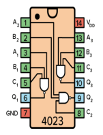
Pin Configuration and Descriptions

Pin Number Pin Name Description
1 A1 Input 1 for NAND Gate 1
2 A2 Input 2 for NAND Gate 1
3 A3 Input 3 for NAND Gate 1
4 A4 Input 4 for NAND Gate 1
5 Y1 Output for NAND Gate 1
6 GND Ground connection
7 A5 Input 1 for NAND Gate 2
8 A6 Input 2 for NAND Gate 2
9 A7 Input 3 for NAND Gate 2
10 A8 Input 4 for NAND Gate 2
11 Y2 Output for NAND Gate 2
12 Vcc Supply voltage connection

Usage Instructions

How to Use the Component in a Circuit

  1. Power Supply: Connect the Vcc pin (Pin 12) to the positive supply voltage (3V to 15V) and the GND pin (Pin 6) to ground.
  2. Input Connections: Connect your input signals to the appropriate input pins (A1 to A4 for NAND Gate 1 and A5 to A8 for NAND Gate 2).
  3. Output Connections: Connect the output pins (Y1 for NAND Gate 1 and Y2 for NAND Gate 2) to the next stage of your circuit.

Important Considerations and Best Practices

  • Ensure that the input voltage levels are within the specified range to avoid damage.
  • Use pull-up or pull-down resistors if necessary to stabilize floating inputs.
  • Keep the total output current below the maximum rating to prevent overheating.
  • For high-speed applications, consider the propagation delay of the NAND gates.

Troubleshooting and FAQs

Common Issues Users Might Face

  1. No Output Signal:

    • Solution: Check power supply connections and ensure that the input signals are within the specified voltage range.
  2. Unexpected Output:

    • Solution: Verify the logic levels of the inputs. Remember that a NAND gate outputs a low signal only when all inputs are high.
  3. Overheating:

    • Solution: Ensure that the output current does not exceed 25 mA and that the IC is not shorted.

Tips for Troubleshooting

  • Use a multimeter to check voltage levels at the input and output pins.
  • If using in a breadboard setup, ensure all connections are secure and not loose.
  • Consult the datasheet for detailed electrical characteristics and timing diagrams.

Example Code for Arduino UNO

If you are using the 4023 NAND gate with an Arduino UNO, here is a simple example code to demonstrate how to read inputs and control an output based on the NAND logic.

// Define pin numbers
const int input1 = 2; // Input A1
const int input2 = 3; // Input A2
const int output = 4; // Output Y1

void setup() {
  pinMode(input1, INPUT); // Set input1 as input
  pinMode(input2, INPUT); // Set input2 as input
  pinMode(output, OUTPUT); // Set output as output
}

void loop() {
  // Read input values
  int val1 = digitalRead(input1);
  int val2 = digitalRead(input2);
  
  // Implement NAND logic
  if (val1 == HIGH && val2 == HIGH) {
    digitalWrite(output, LOW); // Output LOW if both inputs are HIGH
  } else {
    digitalWrite(output, HIGH); // Output HIGH otherwise
  }
}

This code sets up two input pins and one output pin. It reads the state of the inputs and applies the NAND logic to control the output accordingly.