How to Use 2s Bms: Examples, Pinouts, and Specs
Introduction
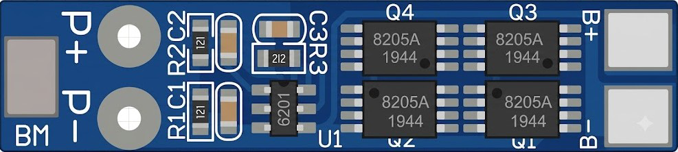
The 2S Battery Management System (BMS) is a compact and essential electronic module designed to manage and protect a two-cell lithium-ion (Li-ion) or lithium-polymer (LiPo) battery pack. It ensures the safe operation of the battery pack by monitoring individual cell voltages, balancing the cells during charging, and providing critical protections such as overcharge, over-discharge, overcurrent, and short-circuit protection.
Explore Projects Built with 2s Bms


Explore Projects Built with 2s Bms
Common Applications and Use Cases
- Power management for portable electronics
- Electric bicycles and scooters
- DIY battery packs for robotics and IoT devices
- Solar energy storage systems
- Uninterruptible Power Supplies (UPS)
Technical Specifications
Below are the key technical details of the 2S BMS:
| Parameter | Value |
|---|---|
| Battery Configuration | 2-series (2S) Li-ion/LiPo cells |
| Input Voltage Range | 7.4V to 8.4V |
| Overcharge Protection | 4.25V ± 0.05V per cell |
| Over-discharge Protection | 2.5V ± 0.05V per cell |
| Maximum Continuous Current | 10A (varies by model) |
| Short-circuit Protection | Yes |
| Balancing Current | ~30mA |
| Operating Temperature Range | -40°C to 85°C |
| Dimensions | Typically 50mm x 20mm x 3mm |
Pin Configuration and Descriptions
The 2S BMS typically has the following pin configuration:
| Pin Name | Description |
|---|---|
| B- | Battery negative terminal (connect to the negative terminal of the battery pack) |
| B1 | Connection point between the two cells in the battery pack |
| B+ | Battery positive terminal (connect to the positive terminal of the battery pack) |
| P- | Power output negative terminal (connect to the load or charger negative) |
| P+ | Power output positive terminal (connect to the load or charger positive) |
Usage Instructions
How to Use the 2S BMS in a Circuit
Connect the Battery Pack:
- Connect the negative terminal of the battery pack to the
B-pin. - Connect the midpoint between the two cells to the
B1pin. - Connect the positive terminal of the battery pack to the
B+pin.
- Connect the negative terminal of the battery pack to the
Connect the Load and Charger:
- Connect the negative terminal of the load or charger to the
P-pin. - Connect the positive terminal of the load or charger to the
P+pin.
- Connect the negative terminal of the load or charger to the
Verify Connections:
- Double-check all connections to ensure proper polarity and secure contacts.
- Ensure the battery pack is within the supported voltage range of the BMS.
Power On:
- Once all connections are secure, the BMS will automatically monitor and manage the battery pack.
Important Considerations and Best Practices
- Cell Matching: Ensure the two cells in the battery pack are of the same capacity, voltage, and chemistry to avoid imbalances.
- Heat Dissipation: Avoid enclosing the BMS in a sealed space without ventilation, as it may generate heat during operation.
- Avoid Overloading: Do not exceed the maximum continuous current rating of the BMS.
- Charging Voltage: Use a charger designed for 2S Li-ion/LiPo batteries with a maximum output of 8.4V.
Example: Using the 2S BMS with an Arduino UNO
The 2S BMS can be used to power an Arduino UNO. Below is an example of how to connect the BMS to the Arduino and monitor the battery voltage:
Circuit Diagram
- Connect the
P+andP-terminals of the BMS to the Arduino's VIN and GND pins, respectively. - Use a voltage divider circuit to measure the battery voltage if needed.
Sample Code
// Arduino code to monitor battery voltage using a voltage divider
const int voltagePin = A0; // Analog pin connected to the voltage divider
const float resistorRatio = 2.0; // Adjust based on your resistor values
const float referenceVoltage = 5.0; // Arduino reference voltage (5V for UNO)

void setup() {
  Serial.begin(9600); // Initialize serial communication
}

void loop() {
  int rawValue = analogRead(voltagePin); // Read the analog value
  float batteryVoltage = (rawValue / 1023.0) * referenceVoltage * resistorRatio;

  // Print the battery voltage to the Serial Monitor
  Serial.print("Battery Voltage: ");
  Serial.print(batteryVoltage);
  Serial.println(" V");

  delay(1000); // Wait for 1 second before the next reading
}
Troubleshooting and FAQs
Common Issues and Solutions
BMS Not Powering On:
- Cause: Incorrect wiring or insufficient battery voltage.
- Solution: Verify all connections and ensure the battery pack voltage is within the supported range.
Over-discharge Protection Triggered:
- Cause: Battery voltage dropped below 2.5V per cell.
- Solution: Recharge the battery pack using a compatible charger.
Overheating:
- Cause: Excessive current draw or poor ventilation.
- Solution: Reduce the load current and ensure proper heat dissipation.
Cells Not Balancing:
- Cause: Significant mismatch in cell capacities or voltages.
- Solution: Replace the cells with a matched pair and ensure proper balancing.
FAQs
Q: Can I use the 2S BMS with other battery chemistries?
A: No, the 2S BMS is specifically designed for Li-ion/LiPo batteries. Using it with other chemistries may result in improper operation or damage.
Q: What happens if I connect the cells in the wrong order?
A: Incorrect wiring can damage the BMS. Always double-check the connections before powering on.
Q: Can I use the BMS for a 3S or 4S battery pack?
A: No, the 2S BMS is only compatible with 2-series battery configurations. For 3S or 4S packs, use a corresponding BMS designed for those configurations.