Cirkit Designer
Your all-in-one circuit design IDE
Home /
Component Documentation
How to Use ESP32-C3-DevKitC-02: Examples, Pinouts, and Specs
Introduction
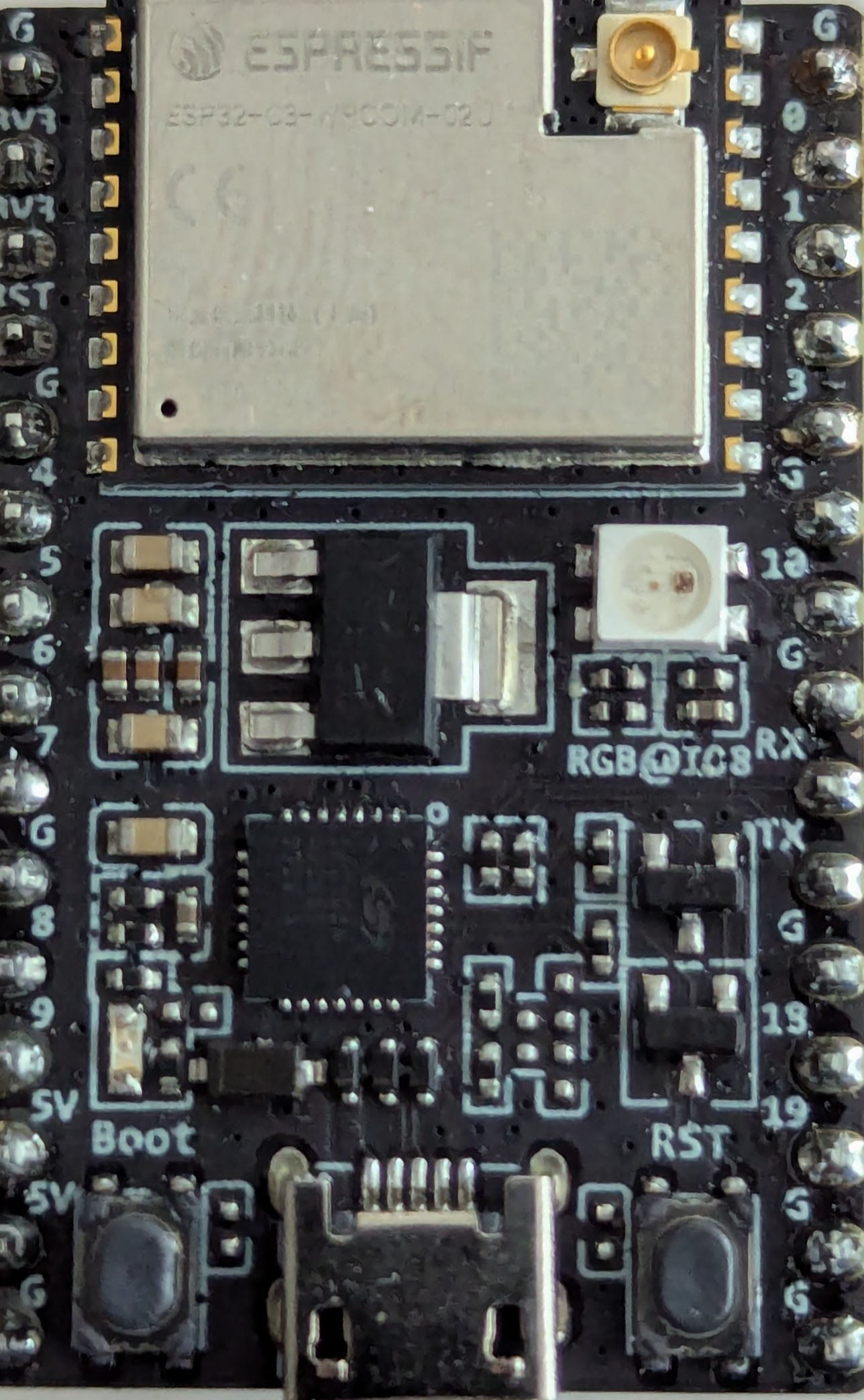
The ESP32-C3-DevKitC-02 is a development board manufactured by Espressif, featuring the ESP32-C3 microcontroller. This microcontroller includes both Wi-Fi and Bluetooth connectivity, making it an ideal choice for IoT applications and prototyping. The board is designed to provide a simple and efficient way to develop and test applications that require wireless communication.
Explore Projects Built with ESP32-C3-DevKitC-02
ESP32-Based Environmental Monitoring and Alert System with Solar Charging

This circuit features an ESP32 Devkit V1 microcontroller connected to various sensors and modules for monitoring and communication purposes. It includes an MQ-2 gas sensor and a DHT11 temperature and humidity sensor, both interfaced with the ESP32 for environmental data collection. The circuit is powered by a 12V battery, regulated to 5V by step-down converters, and includes a solar charge controller connected to a solar panel for battery charging, a UPS module for power management, and a SIM900A module for GSM communication. Additionally, there is a WS2812 RGB LED strip for visual feedback and a piezo buzzer for audio alerts, both controlled by the ESP32.
ESP32-Based Smart Weather and Health Monitoring System with Wi-Fi Connectivity
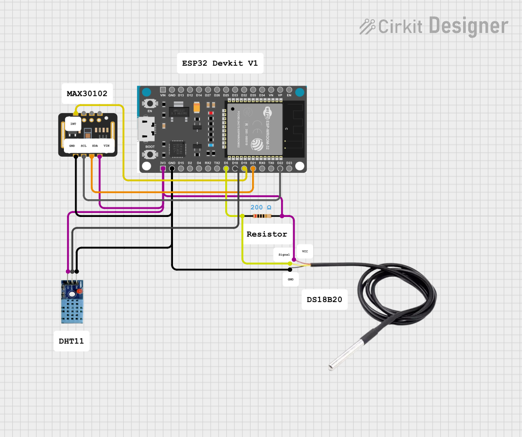
This circuit uses an ESP32 Devkit V1 microcontroller to interface with multiple sensors, including a DHT11 temperature and humidity sensor, a DS18B20 temperature sensor, and a MAX30102 pulse oximeter and heart-rate sensor. The ESP32 reads data from these sensors and can process or transmit the information for further use.
ESP32-Based GPS Tracker with SD Card Logging and Barometric Sensor

This circuit features an ESP32 Wroom Dev Kit as the main microcontroller, interfaced with an MPL3115A2 sensor for pressure and temperature readings, and a Neo 6M GPS module for location tracking. The ESP32 is also connected to an SD card reader for data logging purposes. A voltage regulator is used to step down the USB power supply to 3.3V, which powers the ESP32, the sensor, and the SD card reader.
ESP32-Based Smart Agriculture System with LoRa Communication

This circuit features an ESP32 Devkit V1 microcontroller as the central processing unit, interfacing with various sensors including a PH Meter, an NPK Soil Sensor, and a Soil Moisture Sensor for environmental data collection. It also includes an EBYTE LoRa E220 module for wireless communication. Power management is handled by a Step Up Boost Power Converter, which is connected to a 12V Battery, stepping up the voltage to power the ESP32 and sensors, with common ground connections throughout the circuit.
Explore Projects Built with ESP32-C3-DevKitC-02
ESP32-Based Environmental Monitoring and Alert System with Solar Charging
This circuit features an ESP32 Devkit V1 microcontroller connected to various sensors and modules for monitoring and communication purposes. It includes an MQ-2 gas sensor and a DHT11 temperature and humidity sensor, both interfaced with the ESP32 for environmental data collection. The circuit is powered by a 12V battery, regulated to 5V by step-down converters, and includes a solar charge controller connected to a solar panel for battery charging, a UPS module for power management, and a SIM900A module for GSM communication. Additionally, there is a WS2812 RGB LED strip for visual feedback and a piezo buzzer for audio alerts, both controlled by the ESP32.
ESP32-Based Smart Weather and Health Monitoring System with Wi-Fi Connectivity
This circuit uses an ESP32 Devkit V1 microcontroller to interface with multiple sensors, including a DHT11 temperature and humidity sensor, a DS18B20 temperature sensor, and a MAX30102 pulse oximeter and heart-rate sensor. The ESP32 reads data from these sensors and can process or transmit the information for further use.
ESP32-Based GPS Tracker with SD Card Logging and Barometric Sensor
This circuit features an ESP32 Wroom Dev Kit as the main microcontroller, interfaced with an MPL3115A2 sensor for pressure and temperature readings, and a Neo 6M GPS module for location tracking. The ESP32 is also connected to an SD card reader for data logging purposes. A voltage regulator is used to step down the USB power supply to 3.3V, which powers the ESP32, the sensor, and the SD card reader.
ESP32-Based Smart Agriculture System with LoRa Communication
This circuit features an ESP32 Devkit V1 microcontroller as the central processing unit, interfacing with various sensors including a PH Meter, an NPK Soil Sensor, and a Soil Moisture Sensor for environmental data collection. It also includes an EBYTE LoRa E220 module for wireless communication. Power management is handled by a Step Up Boost Power Converter, which is connected to a 12V Battery, stepping up the voltage to power the ESP32 and sensors, with common ground connections throughout the circuit.
Common Applications and Use Cases
- IoT Devices: Smart home devices, environmental monitoring systems, and industrial IoT applications.
- Prototyping: Rapid development and testing of new ideas and concepts.
- Wireless Communication: Projects requiring Wi-Fi and Bluetooth connectivity.
- Embedded Systems: Integration into larger systems requiring wireless capabilities.
Technical Specifications
Key Technical Details
| Specification | Value |
|---|---|
| Microcontroller | ESP32-C3 |
| Wi-Fi | 802.11 b/g/n |
| Bluetooth | Bluetooth 5.0 LE |
| Operating Voltage | 3.3V |
| Flash Memory | 4MB |
| SRAM | 400KB |
| GPIO Pins | 22 |
| ADC Channels | 6 |
| UART | 2 |
| SPI | 2 |
| I2C | 2 |
| PWM Channels | 6 |
| Operating Temperature | -40°C to 85°C |
Pin Configuration and Descriptions
| Pin Number | Pin Name | Description |
|---|---|---|
| 1 | 3V3 | 3.3V Power Supply |
| 2 | GND | Ground |
| 3 | GPIO0 | General Purpose I/O |
| 4 | GPIO1 | General Purpose I/O |
| 5 | GPIO2 | General Purpose I/O |
| 6 | GPIO3 | General Purpose I/O |
| 7 | GPIO4 | General Purpose I/O |
| 8 | GPIO5 | General Purpose I/O |
| 9 | GPIO6 | General Purpose I/O |
| 10 | GPIO7 | General Purpose I/O |
| 11 | GPIO8 | General Purpose I/O |
| 12 | GPIO9 | General Purpose I/O |
| 13 | GPIO10 | General Purpose I/O |
| 14 | GPIO11 | General Purpose I/O |
| 15 | GPIO12 | General Purpose I/O |
| 16 | GPIO13 | General Purpose I/O |
| 17 | GPIO14 | General Purpose I/O |
| 18 | GPIO15 | General Purpose I/O |
| 19 | GPIO16 | General Purpose I/O |
| 20 | GPIO17 | General Purpose I/O |
| 21 | GPIO18 | General Purpose I/O |
| 22 | GPIO19 | General Purpose I/O |
Usage Instructions
How to Use the Component in a Circuit
- Power Supply: Connect the 3V3 pin to a 3.3V power source and the GND pin to ground.
- GPIO Pins: Use the GPIO pins for input/output operations. These pins can be configured for various functions such as digital I/O, PWM, ADC, etc.
- Programming: Use the UART interface to program the ESP32-C3 microcontroller. You can use the Arduino IDE or Espressif's ESP-IDF for development.
Important Considerations and Best Practices
- Power Supply: Ensure a stable 3.3V power supply to avoid damage to the board.
- GPIO Voltage Levels: The GPIO pins operate at 3.3V logic levels. Avoid applying higher voltages to prevent damage.
- Antenna Placement: For optimal Wi-Fi and Bluetooth performance, ensure that the onboard antenna is not obstructed by metal objects or enclosures.
- Heat Dissipation: Although the ESP32-C3 is designed to operate within a wide temperature range, ensure adequate ventilation to prevent overheating in high-power applications.
Example Code for Arduino UNO
#include <WiFi.h>

// Replace with your network credentials
const char* ssid = "your_SSID";
const char* password = "your_PASSWORD";

void setup() {
  // Initialize serial communication
  Serial.begin(115200);

  // Connect to Wi-Fi
  WiFi.begin(ssid, password);

  // Wait for connection
  while (WiFi.status() != WL_CONNECTED) {
    delay(1000);
    Serial.println("Connecting to WiFi...");
  }

  // Print the IP address
  Serial.println("Connected to WiFi");
  Serial.print("IP Address: ");
  Serial.println(WiFi.localIP());
}

void loop() {
  // Add your main code here, to run repeatedly
}
Troubleshooting and FAQs
Common Issues Users Might Face
Wi-Fi Connection Issues:
- Problem: Unable to connect to Wi-Fi.
- Solution: Ensure the SSID and password are correct. Check if the Wi-Fi network is operational.
Programming Errors:
- Problem: Unable to upload code to the board.
- Solution: Ensure the correct board and port are selected in the Arduino IDE. Check the USB connection.
GPIO Pin Malfunction:
- Problem: GPIO pins not working as expected.
- Solution: Verify the pin configuration in the code. Ensure no short circuits or incorrect connections.
Solutions and Tips for Troubleshooting
- Serial Monitor: Use the Serial Monitor in the Arduino IDE to print debug information and track the program flow.
- Power Supply: Ensure a stable and adequate power supply. Use a dedicated power source if necessary.
- Firmware Updates: Keep the ESP32-C3 firmware updated to the latest version to benefit from bug fixes and improvements.
By following this documentation, users can effectively utilize the ESP32-C3-DevKitC-02 for their IoT and prototyping projects, ensuring optimal performance and reliability.