How to Use 5v UPS DC: Examples, Pinouts, and Specs
Introduction
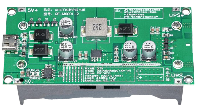
The 5V Uninterruptible Power Supply (UPS) for DC applications is a compact and reliable power management device designed to provide backup power to electronic devices during power outages or fluctuations. It ensures a stable 5V DC output, protecting sensitive electronics from unexpected shutdowns and voltage instability. This component is ideal for use in IoT devices, Raspberry Pi systems, Arduino projects, routers, and other low-power DC applications.
Explore Projects Built with 5v UPS DC


Explore Projects Built with 5v UPS DC
Common Applications and Use Cases
- Backup power for Raspberry Pi, Arduino, and other microcontroller-based systems.
- Ensuring uninterrupted operation of IoT devices during power outages.
- Powering small routers, modems, or network devices.
- Providing stable voltage for sensitive sensors and modules in embedded systems.
- Portable electronics requiring consistent 5V DC power.
Technical Specifications
The following table outlines the key technical details of the 5V UPS DC:
| Parameter | Value |
|---|---|
| Input Voltage | 5V DC (via USB or terminal block) |
| Output Voltage | 5V DC (regulated) |
| Output Current | Up to 2A |
| Battery Type | Lithium-ion (3.7V, 18650) |
| Charging Voltage | 4.2V DC |
| Charging Current | 1A (typical) |
| Backup Time | Depends on battery capacity |
| Protection Features | Overcharge, over-discharge, short circuit |
| Dimensions | Varies by model (e.g., 60mm x 30mm) |
Pin Configuration and Descriptions
The 5V UPS DC typically includes the following pins or connectors:
| Pin/Connector | Description |
|---|---|
| Input (USB/Terminal) | Connects to a 5V DC power source for charging the battery and powering the load. |
| Output (USB/Terminal) | Provides a stable 5V DC output to the connected device. |
| Battery Connector | Connects to a 3.7V lithium-ion battery (e.g., 18650). |
| Status Indicator LEDs | Displays charging, discharging, and fault status. |
Usage Instructions
How to Use the 5V UPS DC in a Circuit
Connect the Input Power Source:
- Use a 5V DC power adapter or USB cable to connect the input terminal or USB port.
- Ensure the input voltage is stable and within the specified range.
Connect the Battery:
- Attach a 3.7V lithium-ion battery (e.g., 18650) to the battery connector.
- Ensure correct polarity to avoid damage to the component.
Connect the Load:
- Connect your device (e.g., Raspberry Pi, Arduino) to the output terminal or USB port.
- Verify that the load does not exceed the maximum output current (2A).
Monitor the Status LEDs:
- Charging LED: Indicates the battery is charging.
- Discharging LED: Indicates the battery is supplying power to the load.
- Fault LED: Indicates an error such as overcurrent or short circuit.
Important Considerations and Best Practices
- Use a high-quality 18650 lithium-ion battery with sufficient capacity for your application.
- Avoid overloading the UPS by connecting devices that draw more than 2A.
- Ensure proper ventilation to prevent overheating during operation.
- Regularly check the battery for wear and replace it if necessary.
- If using with a Raspberry Pi or Arduino, ensure the power draw of connected peripherals is within the UPS's capacity.
Example: Using the 5V UPS DC with an Arduino UNO
Below is an example of how to connect and use the 5V UPS DC with an Arduino UNO. The UPS ensures uninterrupted operation of the Arduino during power outages.
Circuit Connection
- Connect the UPS output to the Arduino's 5V and GND pins.
- Power the UPS input using a 5V DC adapter.
- Attach a 3.7V lithium-ion battery to the UPS battery connector.
Sample Code
// Example code to demonstrate uninterrupted operation of Arduino UNO
// with a 5V UPS DC during power outages.

void setup() {
  pinMode(13, OUTPUT); // Set pin 13 as output for the onboard LED
  digitalWrite(13, HIGH); // Turn on the LED to indicate power is ON
}

void loop() {
  // Simulate normal operation
  delay(1000); // Wait for 1 second
  digitalWrite(13, LOW); // Turn off the LED
  delay(1000); // Wait for 1 second
  digitalWrite(13, HIGH); // Turn on the LED
}
This code ensures the Arduino continues to operate normally even if the main power source is interrupted, as the UPS will seamlessly switch to battery power.
Troubleshooting and FAQs
Common Issues and Solutions
| Issue | Possible Cause | Solution |
|---|---|---|
| No output power | Battery not connected or depleted | Check battery connection and charge the battery. |
| Output voltage unstable | Overloaded UPS or faulty battery | Reduce the load or replace the battery. |
| UPS overheating | Insufficient ventilation or high load | Ensure proper ventilation and reduce the load if necessary. |
| Fault LED is ON | Short circuit or overcurrent detected | Disconnect the load, check for shorts, and reconnect after resolving issue. |
FAQs
Can I use a different battery type?
No, the UPS is designed for 3.7V lithium-ion batteries. Using other types may damage the device.What is the maximum backup time?
The backup time depends on the battery capacity and the load. For example, a 3000mAh battery can provide approximately 1.5 hours of backup at a 2A load.Can I use the UPS without a battery?
No, the UPS requires a battery to function as a backup power source during outages.Is the UPS safe for sensitive electronics?
Yes, the UPS includes protection features such as overcharge, over-discharge, and short circuit protection to ensure safe operation.
By following this documentation, you can effectively integrate the 5V UPS DC into your projects and ensure reliable power delivery for your devices.