How to Use Dual Digit 14-segment Alphanumeric LED Display: Examples, Pinouts, and Specs
Introduction
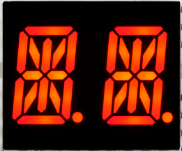
The Luckylight KWA-541CVB is a dual-digit 14-segment alphanumeric LED display module. Each digit is capable of displaying letters, numbers, and some special characters, making it ideal for applications requiring clear and versatile text or numeric output. The display uses 14 individual segments per digit to create a wide range of characters.
Explore Projects Built with Dual Digit 14-segment Alphanumeric LED Display
Explore Projects Built with Dual Digit 14-segment Alphanumeric LED Display
Common Applications
- Digital clocks and timers
- Counters and scoreboards
- Industrial control panels
- Consumer electronics (e.g., microwave ovens, audio equipment)
- Embedded systems requiring alphanumeric output
Technical Specifications
The following table outlines the key technical details of the KWA-541CVB:
| Parameter | Value |
|---|---|
| Manufacturer | Luckylight |
| Part Number | KWA-541CVB |
| Display Type | 14-segment alphanumeric, dual digit |
| LED Color | Blue |
| Forward Voltage (VF) | 2.0V to 2.4V per segment |
| Forward Current (IF) | 20mA per segment (typical) |
| Peak Forward Current | 100mA (1/10 duty cycle, 0.1ms pulse width) |
| Reverse Voltage (VR) | 5V |
| Operating Temperature | -40°C to +85°C |
| Dimensions | 19.0mm x 12.6mm x 8.0mm |
| Pin Count | 18 pins |
Pin Configuration and Descriptions
The KWA-541CVB has 18 pins, which include segment control pins, digit selection pins, and common cathode connections. The pinout is as follows:
| Pin Number | Function | Description |
|---|---|---|
| 1 | A1 | Segment A of Digit 1 |
| 2 | F1 | Segment F of Digit 1 |
| 3 | K1 | Segment K of Digit 1 |
| 4 | E1 | Segment E of Digit 1 |
| 5 | D1 | Segment D of Digit 1 |
| 6 | DP1 | Decimal Point of Digit 1 |
| 7 | C1 | Segment C of Digit 1 |
| 8 | G1 | Segment G of Digit 1 |
| 9 | Cathode 1 | Common Cathode for Digit 1 |
| 10 | Cathode 2 | Common Cathode for Digit 2 |
| 11 | G2 | Segment G of Digit 2 |
| 12 | C2 | Segment C of Digit 2 |
| 13 | DP2 | Decimal Point of Digit 2 |
| 14 | D2 | Segment D of Digit 2 |
| 15 | E2 | Segment E of Digit 2 |
| 16 | K2 | Segment K of Digit 2 |
| 17 | F2 | Segment F of Digit 2 |
| 18 | A2 | Segment A of Digit 2 |
Usage Instructions
How to Use the Component in a Circuit
- Power Requirements: Ensure that the forward voltage (2.0V to 2.4V) and forward current (20mA per segment) are met. Use current-limiting resistors to prevent overdriving the LEDs.
- Driving the Segments: Each segment is controlled individually. Apply a forward voltage to the desired segment pin and connect the corresponding cathode pin to ground.
- Multiplexing: To control both digits, use a multiplexing technique. Activate one digit at a time by connecting its cathode to ground while driving the desired segments.
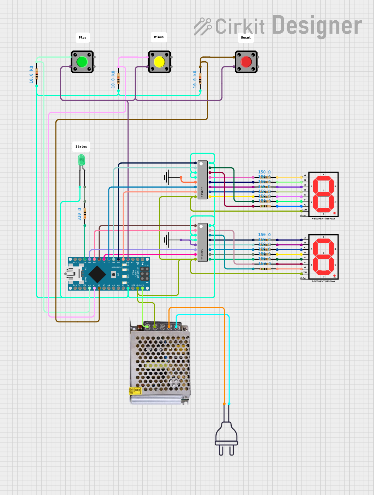
- Microcontroller Interface: Use GPIO pins from a microcontroller (e.g., Arduino UNO) to control the segments. A shift register or LED driver IC can simplify the wiring.
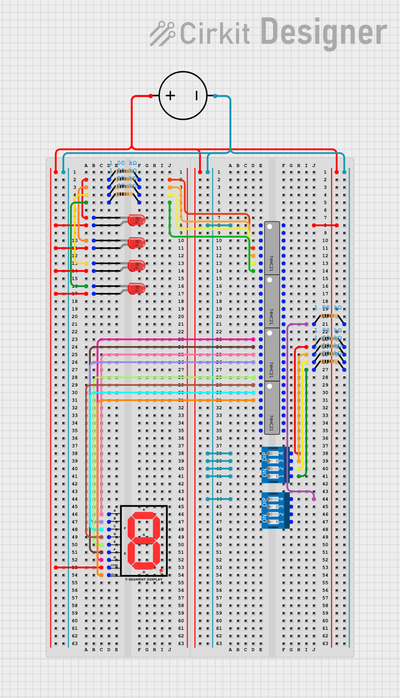
Example Circuit with Arduino UNO
Below is an example of how to connect and control the KWA-541CVB using an Arduino UNO:
Circuit Connections
- Connect segment pins (A1, B1, etc.) to Arduino digital pins via 220Ω resistors.
- Connect Cathode 1 and Cathode 2 to two separate Arduino digital pins.
Arduino Code
// Define segment pins for Digit 1
const int segPins1[] = {2, 3, 4, 5, 6, 7, 8}; // A1, B1, C1, D1, E1, F1, G1
// Define segment pins for Digit 2
const int segPins2[] = {9, 10, 11, 12, 13, A0, A1}; // A2, B2, C2, D2, E2, F2, G2
// Define cathode pins
const int cathodePins[] = {A2, A3}; // Cathode 1 and Cathode 2

// Character segment map (example for '0' and '1')
const byte charMap[2][7] = {
  {1, 1, 1, 1, 1, 1, 0}, // '0'
  {0, 1, 1, 0, 0, 0, 0}  // '1'
};

void setup() {
  // Set segment pins as outputs
  for (int i = 0; i < 7; i++) {
    pinMode(segPins1[i], OUTPUT);
    pinMode(segPins2[i], OUTPUT);
  }
  // Set cathode pins as outputs
  for (int i = 0; i < 2; i++) {
    pinMode(cathodePins[i], OUTPUT);
  }
}

void loop() {
  // Display '0' on Digit 1
  digitalWrite(cathodePins[0], LOW); // Enable Digit 1
  for (int i = 0; i < 7; i++) {
    digitalWrite(segPins1[i], charMap[0][i]);
  }
  delay(1000); // Hold for 1 second

  // Display '1' on Digit 2
  digitalWrite(cathodePins[0], HIGH); // Disable Digit 1
  digitalWrite(cathodePins[1], LOW);  // Enable Digit 2
  for (int i = 0; i < 7; i++) {
    digitalWrite(segPins2[i], charMap[1][i]);
  }
  delay(1000); // Hold for 1 second
}
Important Considerations
- Use appropriate resistors to limit current through each segment.
- Avoid exceeding the maximum forward current to prevent damage.
- If using multiplexing, ensure the refresh rate is high enough to avoid flickering.
Troubleshooting and FAQs
Common Issues
Segments Not Lighting Up:
- Check the connections and ensure the correct pins are connected.
- Verify that the current-limiting resistors are properly installed.
- Ensure the forward voltage is within the specified range.
Flickering Display:
- Increase the refresh rate if using multiplexing.
- Check for loose connections or poor solder joints.
Dim Segments:
- Verify that the current through each segment is sufficient (20mA typical).
- Check the resistor values and ensure they are not too high.
FAQs
Q: Can I use this display with a 3.3V microcontroller?
A: Yes, but ensure the forward voltage of the LEDs is met. You may need to adjust resistor values accordingly.
Q: How do I display letters like 'A' or 'B'?
A: Create a segment map for each character by determining which segments need to be lit. Use the map to control the segments programmatically.
Q: Can I control this display without multiplexing?
A: Yes, but you will need a separate set of GPIO pins for each digit, which may not be practical for microcontrollers with limited pins.