How to Use Arcade Button (red): Examples, Pinouts, and Specs
Introduction
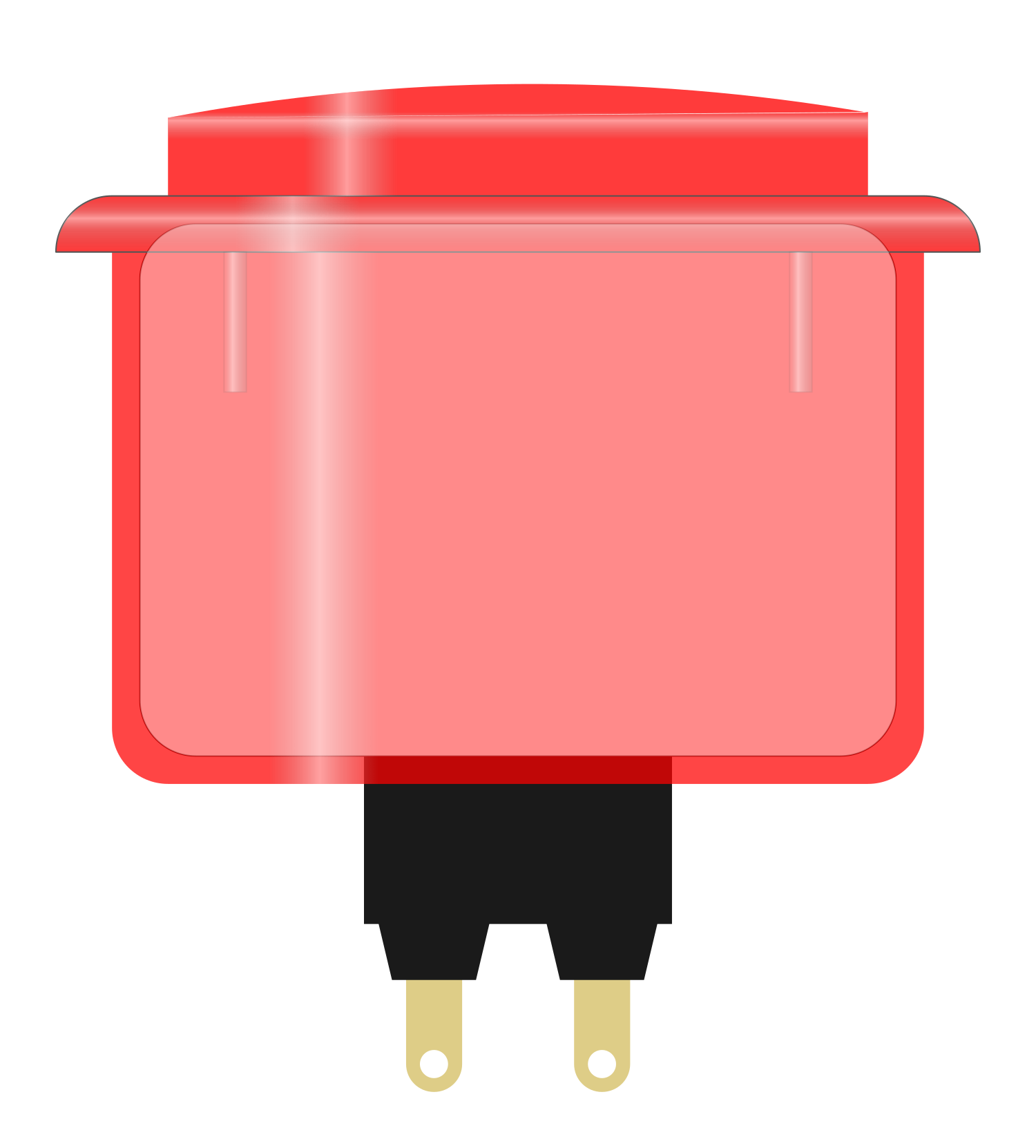
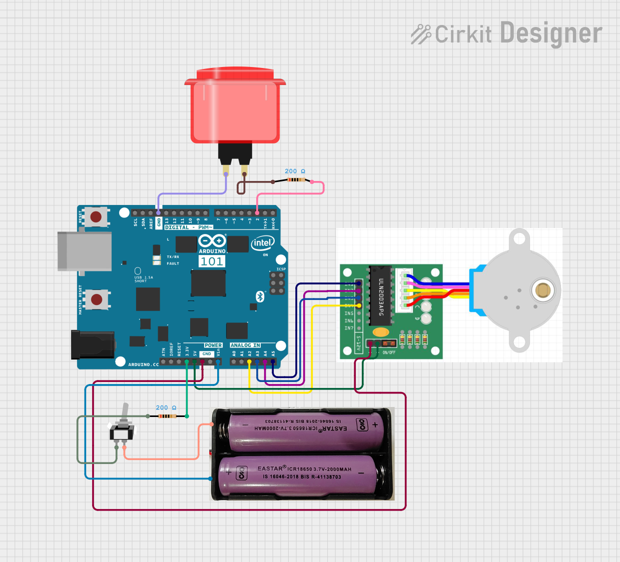
The Arcade Button (red) is a large, robust push button switch designed for heavy use in arcade game machines. Its durable design and responsive actuation make it ideal for interactive projects, including DIY arcade cabinets, game controllers, and educational platforms where a reliable and user-friendly interface is essential.
Explore Projects Built with Arcade Button (red)
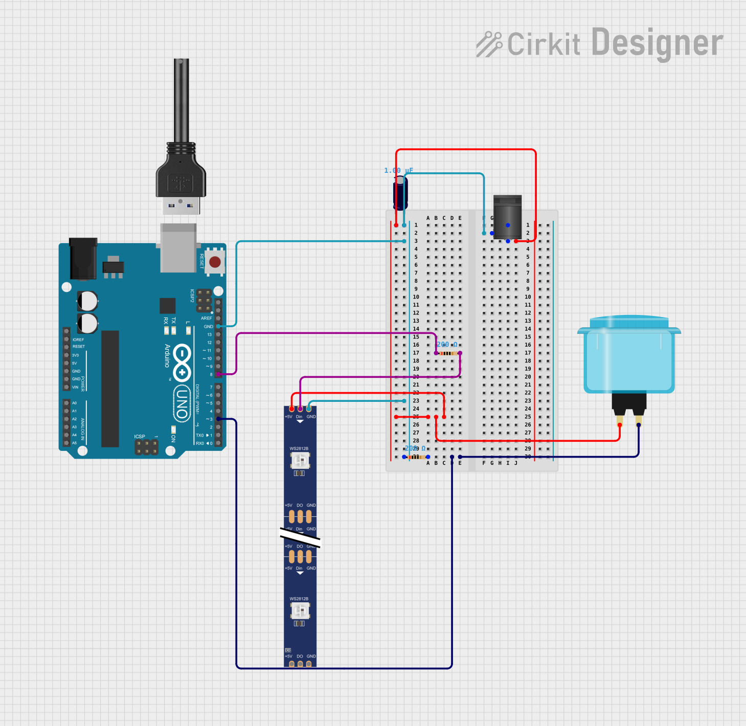
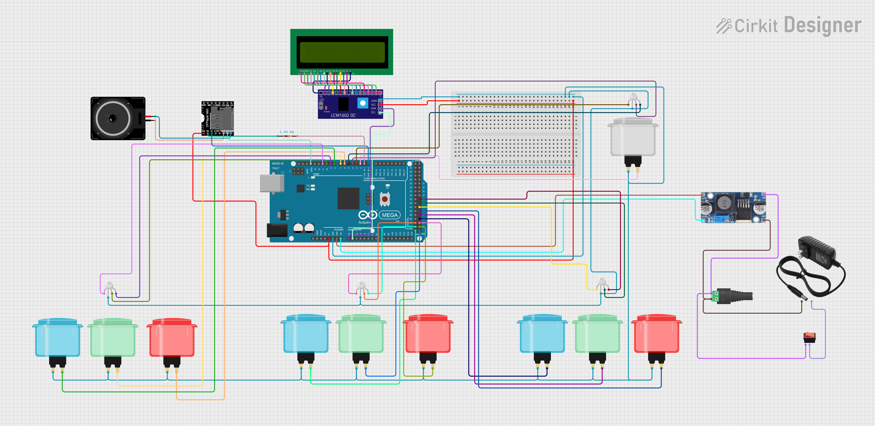
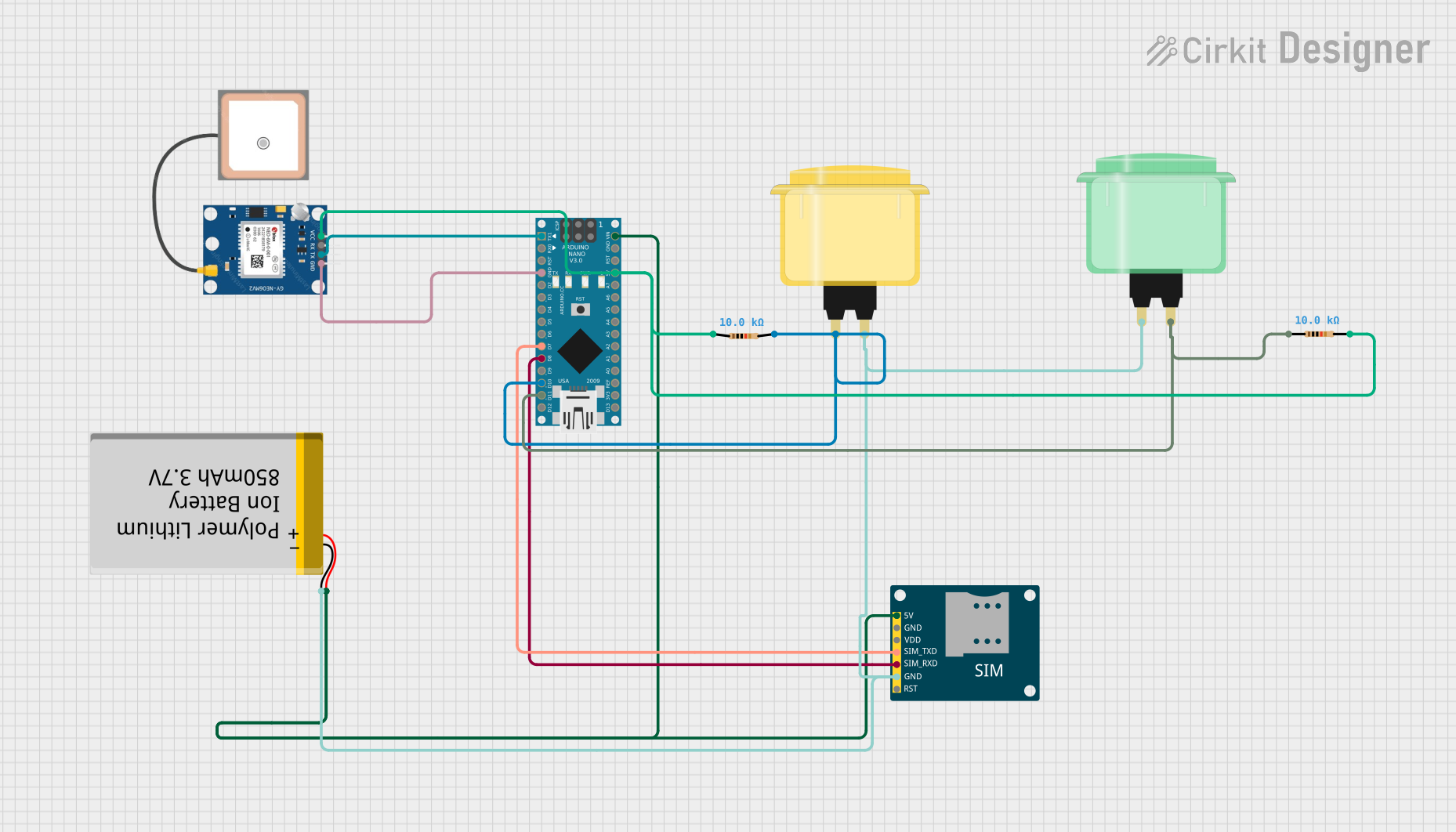
Explore Projects Built with Arcade Button (red)
Common Applications and Use Cases
- Arcade game machines
- Custom game controllers
- Interactive exhibits
- Educational projects
- DIY electronics projects
Technical Specifications
Key Technical Details
- Switch Type: Momentary push button
- Color: Red
- Material: Plastic (typically ABS)
- Contact Type: Normally open (NO)
- Mounting Type: Panel mount
- Actuation Force: Approximately 50-70 grams
- Life Expectancy: 1 million cycles
- Operating Temperature: -10°C to +70°C
Pin Configuration and Descriptions
| Pin Number | Description | Notes |
|---|---|---|
| 1 | Common (COM) | Connect to ground (-) |
| 2 | Normally Open (NO) | Connect to signal input |
Usage Instructions
How to Use the Component in a Circuit
- Mounting the Button: Secure the arcade button into a panel with the provided nut. Ensure it is tight and stable.
- Wiring: Connect the COM pin to the ground of your circuit. Connect the NO pin to the input pin on your microcontroller or interface circuit.
- Debounce: Implement a debounce algorithm in your software to ensure reliable button press detection.
Important Considerations and Best Practices
- Voltage and Current Ratings: Ensure that the voltage and current applied to the button do not exceed the manufacturer's specifications.
- Debouncing: Buttons can produce spurious open/close signals when pressed. Software debouncing or hardware debouncing circuits are recommended.
- Mounting: Ensure the button is mounted securely to prevent movement during use.
Example Code for Arduino UNO
// Define the pin where the button is connected
const int buttonPin = 2;
// Variable to hold the button state
int buttonState = 0;

void setup() {
  // Initialize the button pin as an input
  pinMode(buttonPin, INPUT);
  // Initialize serial communication at 9600 bits per second
  Serial.begin(9600);
}

void loop() {
  // Read the state of the button
  buttonState = digitalRead(buttonPin);

  // Check if the button is pressed
  if (buttonState == HIGH) {
    // If the button is pressed, print this message
    Serial.println("Button Pressed");
    // Delay a little bit to avoid bouncing
    delay(50);
  }
}
Troubleshooting and FAQs
Common Issues Users Might Face
- Button does not respond: Ensure the button is wired correctly and the pins are not shorted.
- Intermittent button presses: This is likely due to switch bounce. Implement a debounce algorithm in your code.
- Button sticks when pressed: Check if the button is mounted correctly and that there is no debris causing obstruction.
Solutions and Tips for Troubleshooting
- Check Connections: Verify all connections are secure and correct.
- Debounce Code: Implement debounce code to handle mechanical switch bounce.
- Inspect for Damage: If the button has been heavily used, inspect for physical wear and replace if necessary.
FAQs
Q: Can I use the arcade button with a 12V system? A: Yes, but ensure that the current does not exceed the button's maximum rating.
Q: How do I know if my button is working? A: You can use a multimeter to test continuity between the COM and NO pins when the button is pressed.
Q: Can I use the arcade button with a Raspberry Pi? A: Yes, the arcade button can be used with a Raspberry Pi or any other microcontroller with appropriate input voltage levels and input pin configuration.