How to Use Micro Switch Hinge Roller: Examples, Pinouts, and Specs
Introduction
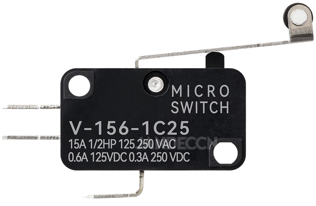
The Micro Switch Hinge Roller (Manufacturer: JANDECCN, Part ID: V-156-1C25) is a compact and reliable mechanical switch designed for precise actuation. It features a hinge roller actuator, which allows for smooth and consistent operation in a variety of applications. This switch is widely used in industrial machinery, home appliances, and automation systems where accurate and repeatable switching is required.
Explore Projects Built with Micro Switch Hinge Roller
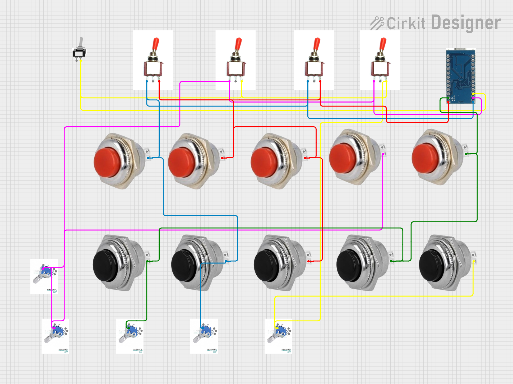

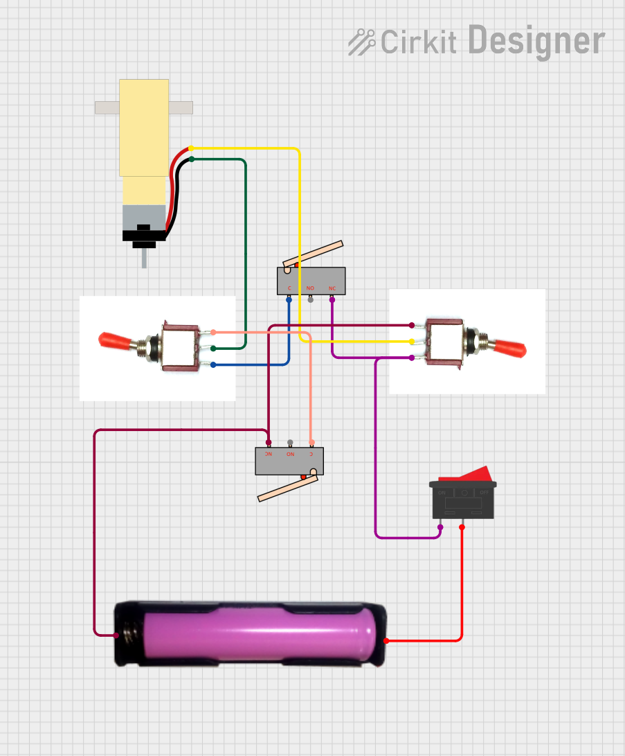

Explore Projects Built with Micro Switch Hinge Roller
Common Applications and Use Cases
- Limit switches in industrial automation
- Position detection in mechanical systems
- Safety interlocks in appliances
- Robotics and mechatronics
- Door or lever position sensing
Technical Specifications
The following table outlines the key technical details of the JANDECCN V-156-1C25 micro switch:
| Parameter | Specification |
|---|---|
| Actuator Type | Hinge Roller |
| Contact Configuration | SPDT (Single Pole Double Throw) |
| Rated Voltage | 250V AC / 125V AC |
| Rated Current | 15A |
| Mechanical Life | 1,000,000 cycles |
| Electrical Life | 50,000 cycles |
| Operating Force (OF) | 400 gf (gram-force) |
| Terminal Type | Quick Connect (Solder Lug) |
| Operating Temperature | -25°C to +85°C |
| Dimensions | 27.8mm x 10.3mm x 15.9mm |
Pin Configuration and Descriptions
The micro switch has three terminals, as described in the table below:
| Pin Name | Description |
|---|---|
| COM | Common terminal. This is the main input terminal for the switch. |
| NO | Normally Open terminal. This terminal is connected to COM when the switch is activated. |
| NC | Normally Closed terminal. This terminal is connected to COM when the switch is not activated. |
Usage Instructions
How to Use the Component in a Circuit
- Identify the Terminals: Locate the COM, NO, and NC terminals on the switch.
- Connect the Circuit:
- For a normally open (NO) configuration, connect the load between the NO and COM terminals. The circuit will close when the switch is actuated.
- For a normally closed (NC) configuration, connect the load between the NC and COM terminals. The circuit will open when the switch is actuated.
- Mount the Switch: Secure the switch in place using screws or a mounting bracket. Ensure the hinge roller is aligned with the mechanical actuator (e.g., a lever or cam).
- Test the Switch: Manually actuate the hinge roller to verify proper operation of the circuit.
Important Considerations and Best Practices
- Voltage and Current Ratings: Ensure the connected load does not exceed the rated voltage (250V AC) or current (15A) of the switch.
- Debouncing: If the switch is used in a digital circuit, consider implementing debouncing techniques to avoid false triggering due to mechanical bounce.
- Environmental Conditions: Avoid exposing the switch to extreme temperatures, moisture, or corrosive environments beyond its specified operating range.
- Secure Connections: Use appropriate soldering techniques or quick-connect terminals to ensure reliable electrical connections.
Example: Connecting to an Arduino UNO
The micro switch can be used as an input device for an Arduino UNO. Below is an example circuit and code to detect the switch's state:
Circuit Diagram
- Connect the COM terminal of the switch to the GND pin of the Arduino.
- Connect the NO terminal of the switch to digital pin 2 of the Arduino.
- Use a pull-up resistor (10kΩ) between digital pin 2 and the 5V pin of the Arduino.
Arduino Code
// Micro Switch Example with Arduino UNO
// This code reads the state of the micro switch and prints it to the Serial Monitor.

const int switchPin = 2; // Pin connected to the NO terminal of the switch
int switchState = 0;     // Variable to store the switch state

void setup() {
  pinMode(switchPin, INPUT_PULLUP); // Set the pin as input with internal pull-up resistor
  Serial.begin(9600);              // Initialize serial communication
}

void loop() {
  switchState = digitalRead(switchPin); // Read the state of the switch

  if (switchState == LOW) {
    // Switch is pressed (NO terminal connected to COM)
    Serial.println("Switch is ON");
  } else {
    // Switch is not pressed (NO terminal disconnected from COM)
    Serial.println("Switch is OFF");
  }

  delay(100); // Small delay to avoid spamming the Serial Monitor
}
Troubleshooting and FAQs
Common Issues and Solutions
Switch Not Activating Properly:
- Cause: Misalignment of the hinge roller with the actuator.
- Solution: Adjust the mounting position to ensure proper alignment.
Intermittent Operation:
- Cause: Loose or poor electrical connections.
- Solution: Check and secure all connections. Use solder or quick-connect terminals as needed.
Switch Fails to Close/Open Circuit:
- Cause: Exceeding the rated current or voltage, causing internal damage.
- Solution: Replace the switch and ensure the load is within the specified ratings.
Mechanical Wear:
- Cause: Prolonged use or excessive force on the hinge roller.
- Solution: Replace the switch if the mechanical life has been exceeded.
FAQs
Q1: Can this switch handle DC loads?
A1: Yes, the switch can handle DC loads, but ensure the voltage and current ratings are within the specified limits.
Q2: How do I debounce the switch in software?
A2: You can use a small delay (e.g., 10-50ms) in your code after detecting a state change to filter out mechanical bounce.
Q3: Can the switch be used outdoors?
A3: The switch is not waterproof or weatherproof. Use it in a protected environment or consider an enclosure for outdoor applications.
Q4: What is the purpose of the hinge roller?
A4: The hinge roller allows for smoother actuation and reduces wear when the switch is triggered by a moving part, such as a cam or lever.