
How to Use SO-32W: Examples, Pinouts, and Specs
 Design with SO-32W in Cirkit Designer
Introduction
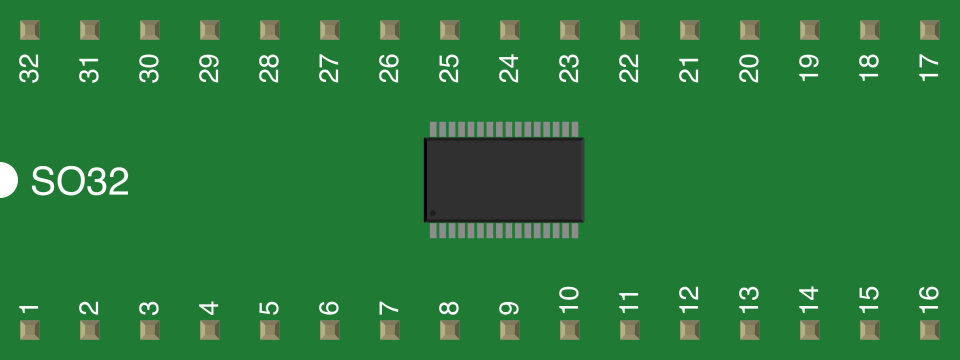
The SO-32W (Small Outline Package, 32 Wide) is a surface-mount package with 32 pins, designed for compact and efficient integration of integrated circuits (ICs) in modern electronic devices. Manufactured by Generic, this package is widely used in applications requiring high pin density and reduced PCB space. Its wide-body design provides additional spacing between pins, making it suitable for applications with higher voltage isolation requirements.
Explore Projects Built with SO-32W
 Open Project in Cirkit Designer
 Open Project in Cirkit Designer
 Open Project in Cirkit Designer
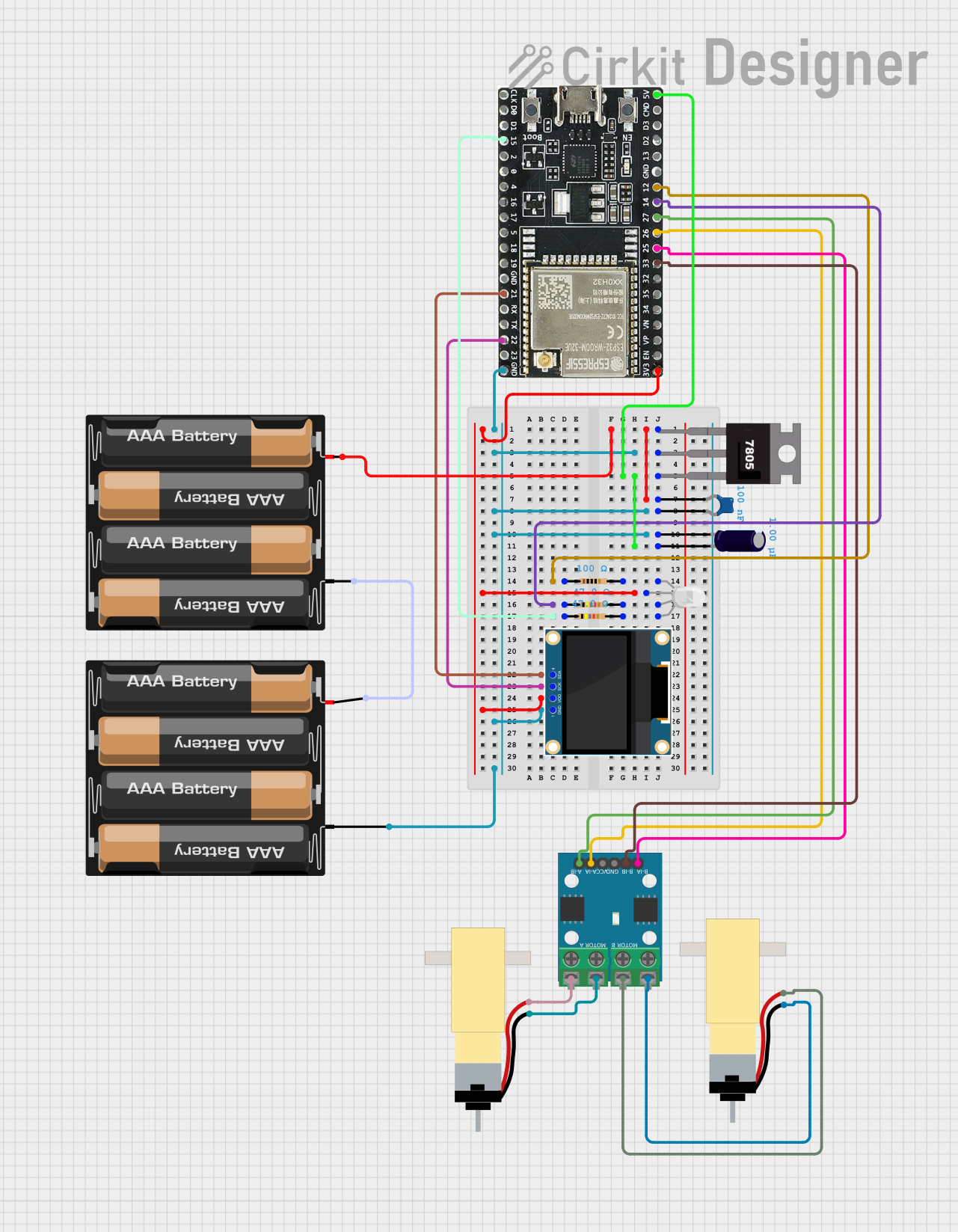 Open Project in Cirkit Designer
Explore Projects Built with SO-32W
Open Project in Cirkit DesignerOpen Project in Cirkit DesignerOpen Project in Cirkit DesignerOpen Project in Cirkit DesignerCommon Applications and Use Cases
- Microcontrollers and digital signal processors (DSPs)
- Memory ICs (e.g., EEPROM, Flash)
- Analog and mixed-signal ICs
- Power management ICs
- Communication modules in consumer electronics
- Automotive and industrial control systems
Technical Specifications
Key Technical Details
| Parameter | Value |
|---|---|
| Manufacturer | Generic |
| Part ID | SO-32W |
| Package Type | Surface-Mount (Wide Body) |
| Number of Pins | 32 |
| Pin Pitch | 1.27 mm |
| Body Width | 7.5 mm |
| Body Length | 20 mm |
| Maximum Height | 2.65 mm |
| Operating Temperature | -40°C to +125°C |
| Maximum Voltage Rating | 50V |
| Maximum Current Rating | 500 mA per pin |
| Thermal Resistance | 50°C/W (junction to ambient) |
Pin Configuration and Descriptions
The SO-32W package has 32 pins arranged in two parallel rows. Below is a generic pinout description for ICs using this package. Note that the specific pin functions depend on the IC housed in the SO-32W package.
| Pin Number | Pin Name | Description |
|---|---|---|
| 1 | VCC | Power supply input |
| 2 | GND | Ground |
| 3-8 | I/O1-I/O6 | General-purpose input/output pins |
| 9 | RESET | Reset input |
| 10-16 | DATA1-DATA7 | Data bus pins |
| 17 | CLK | Clock input |
| 18-24 | ADDR1-ADDR7 | Address bus pins |
| 25 | CS | Chip select |
| 26 | RD | Read enable |
| 27 | WR | Write enable |
| 28-32 | NC | No connection (reserved for future use) |
Note: Always refer to the datasheet of the specific IC housed in the SO-32W package for exact pin assignments.
Usage Instructions
How to Use the SO-32W in a Circuit
- PCB Design: Ensure your PCB layout matches the SO-32W footprint. The pin pitch is 1.27 mm, and the wide-body design requires a body width of 7.5 mm.
- Soldering: Use surface-mount soldering techniques such as reflow soldering. Ensure proper alignment of the pins to avoid shorts or open connections.
- Power Supply: Verify that the power supply voltage and current ratings are within the specified limits of the IC housed in the SO-32W package.
- Decoupling Capacitors: Place decoupling capacitors (e.g., 0.1 µF) close to the VCC and GND pins to reduce noise and stabilize the power supply.
- Signal Integrity: Use proper trace routing techniques to minimize crosstalk and signal interference, especially for high-speed signals.
Important Considerations and Best Practices
- Thermal Management: Ensure adequate heat dissipation by using thermal vias or heat sinks if the IC generates significant heat.
- Pin Protection: Use pull-up or pull-down resistors on unused pins to prevent floating states.
- ESD Protection: Handle the component with care to avoid electrostatic discharge damage.
- Programming and Debugging: If the IC is programmable, ensure access to programming/debugging pins during PCB design.
Example: Connecting an SO-32W IC to an Arduino UNO
Below is an example of interfacing an SO-32W IC (e.g., a memory IC) with an Arduino UNO. This example assumes the IC uses SPI communication.
#include <SPI.h> // Include the SPI library for communication

#define CS_PIN 10 // Define the Chip Select pin for the SO-32W IC

void setup() {
  pinMode(CS_PIN, OUTPUT); // Set the CS pin as an output
  digitalWrite(CS_PIN, HIGH); // Set CS pin to HIGH (inactive)

  SPI.begin(); // Initialize SPI communication
  Serial.begin(9600); // Initialize serial communication for debugging
}

void loop() {
  digitalWrite(CS_PIN, LOW); // Activate the SO-32W IC by pulling CS low
  SPI.transfer(0x9F); // Example: Send a command to read the IC's ID
  byte response = SPI.transfer(0x00); // Read the response from the IC
  digitalWrite(CS_PIN, HIGH); // Deactivate the IC by pulling CS high

  Serial.print("IC Response: 0x");
  Serial.println(response, HEX); // Print the response in hexadecimal format

  delay(1000); // Wait for 1 second before repeating
}
Note: Modify the SPI commands and pin connections based on the specific IC housed in the SO-32W package.
Troubleshooting and FAQs
Common Issues and Solutions
Issue: Pins are not properly soldered, leading to intermittent connections.
- Solution: Inspect the solder joints under a microscope and reflow solder if necessary.
Issue: The IC does not respond to commands.
- Solution: Verify the power supply voltage, clock signal, and communication protocol settings.
Issue: Excessive heat generation during operation.
- Solution: Check for overvoltage or overcurrent conditions. Improve thermal management.
Issue: Signal interference or noise on high-speed lines.
- Solution: Use proper trace routing techniques and add decoupling capacitors.
FAQs
Q1: Can the SO-32W package be hand-soldered?
A1: Yes, but it requires precision and experience. Using a fine-tip soldering iron and flux is recommended.
Q2: What is the advantage of the wide-body design?
A2: The wide-body design provides better voltage isolation and allows for larger internal die sizes.
Q3: How do I identify pin 1 on the SO-32W package?
A3: Pin 1 is typically marked with a dot or a chamfered corner on the package.
Q4: Can I use the SO-32W package for high-frequency applications?
A4: Yes, but ensure proper PCB design to minimize signal integrity issues.
Q5: Is the SO-32W package compatible with automated pick-and-place machines?
A5: Yes, the SO-32W package is designed for automated assembly processes.