How to Use Atribot: Examples, Pinouts, and Specs
Introduction
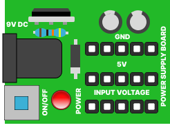
The Atribot Power Supply Board is a sophisticated electronic component designed for advanced signal processing and data analysis within electronic circuits. Known for its high precision and reliability, the Atribot is an essential component in a wide range of applications, from robotics and automation to data acquisition systems and complex computational tasks.
Explore Projects Built with Atribot
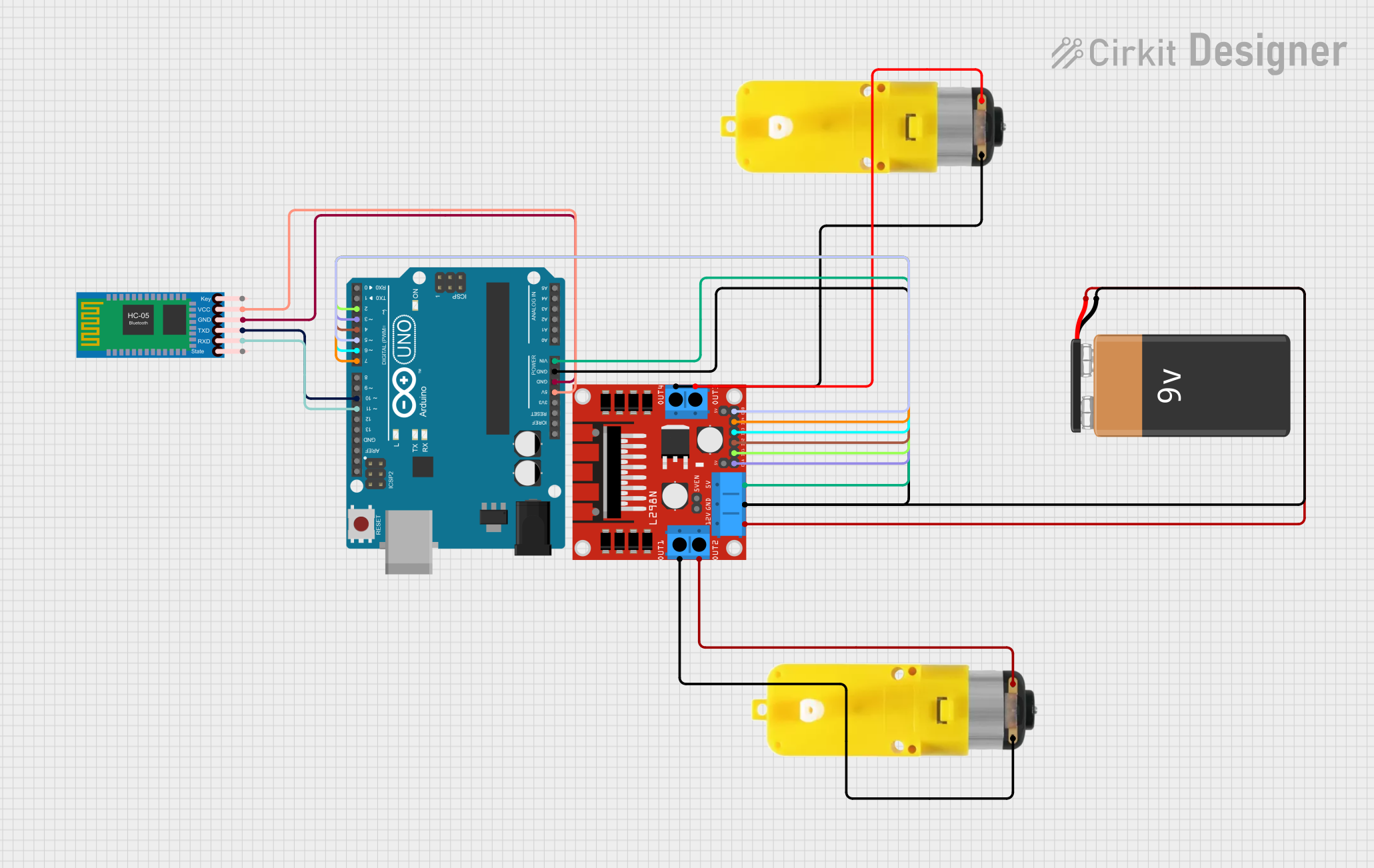
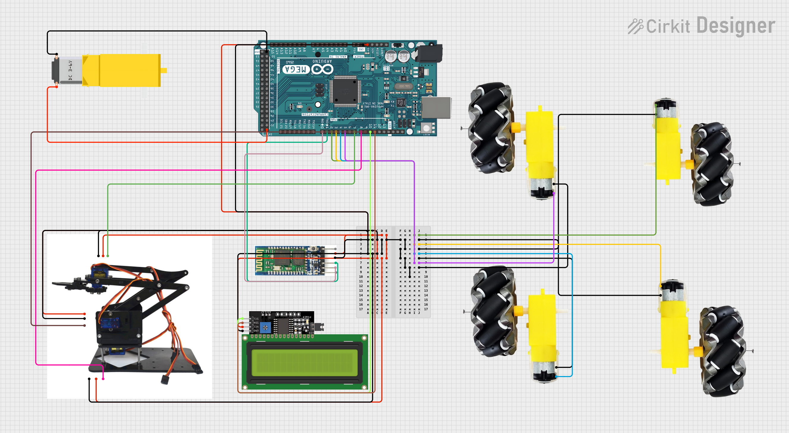
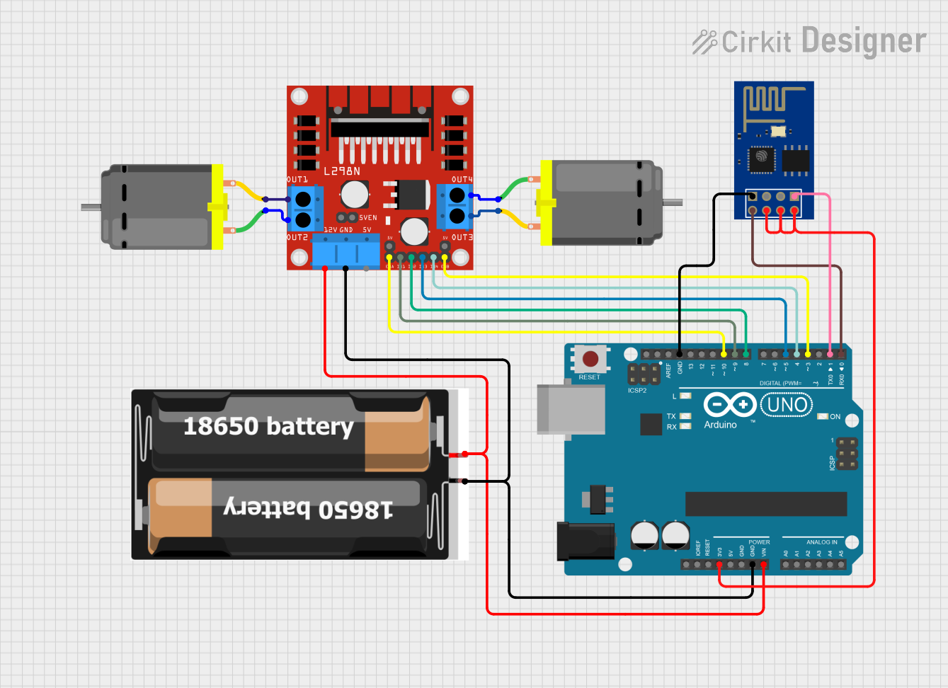
Explore Projects Built with Atribot
Common Applications and Use Cases
- Robotics and automation control systems
- Data acquisition and signal processing units
- High-precision measurement equipment
- Power management in complex electronic systems
- Research and development projects requiring stable power supply
Technical Specifications
Key Technical Details
- Input Voltage Range: 6V to 12V DC
- Output Voltage: 5V DC regulated
- Maximum Output Current: 2A
- Power Ratings: 10W (max)
- Operating Temperature: -20°C to 85°C
- Dimensions: 75mm x 55mm x 25mm
Pin Configuration and Descriptions
| Pin Number | Name | Description |
|---|---|---|
| 1 | VIN | Input voltage (6-12V DC) |
| 2 | GND | Ground connection |
| 3 | VOUT | Regulated 5V output |
| 4 | EN | Enable pin (active high) |
| 5 | FLT | Fault indicator (active low) |
Usage Instructions
How to Use the Component in a Circuit
- Power Input: Connect a DC power source within the specified input voltage range to the VIN and GND pins.
- Power Output: Connect the VOUT and GND pins to the power input of your target circuit or device.
- Enable Pin: Apply a high signal (5V) to the EN pin to enable the power output. Leave unconnected or connect to ground to disable.
- Fault Indicator: Connect the FLT pin to an LED or a digital input on a microcontroller to monitor the status of the power supply.
Important Considerations and Best Practices
- Ensure that the input voltage does not exceed the maximum rating to prevent damage.
- Do not overload the power supply; ensure the total current draw is within the output current limit.
- Use proper heat dissipation techniques if operating near the maximum power rating.
- Avoid exposing the board to temperatures outside the specified operating range.
- Use decoupling capacitors close to the power inputs of sensitive components to minimize noise.
Troubleshooting and FAQs
Common Issues
- No Output Voltage: Ensure the input voltage is within the specified range and the EN pin is activated.
- Overheating: Check if the current draw is within the limit and improve heat dissipation if necessary.
- Intermittent Operation: Verify connections and solder joints for any loose or cold solder points.
Solutions and Tips for Troubleshooting
- If the FLT pin is active, check for short circuits or overcurrent conditions in your circuit.
- Use a multimeter to verify the input voltage and the presence of the output voltage.
- Ensure that the EN pin is receiving a high signal if the output is enabled.
FAQs
Q: Can I use the Atribot Power Supply Board with an Arduino UNO? A: Yes, the board can be used to provide a stable 5V supply to an Arduino UNO or similar microcontroller boards.
Q: What should I do if the board is not outputting the correct voltage? A: Check the input voltage, ensure the EN pin is high, and that there are no faults indicated by the FLT pin.
Q: Is it possible to adjust the output voltage? A: The Atribot Power Supply Board provides a fixed 5V output. For a variable output, an additional voltage regulator would be required.
Example Arduino UNO Connection
// Connect the Atribot Power Supply Board to the Arduino UNO as follows:
// Atribot VIN to external power supply (6-12V)
// Atribot GND to external power supply ground and Arduino GND
// Atribot VOUT to Arduino 5V pin
// Atribot EN to Arduino digital pin (e.g., pin 7) or directly to 5V if always enabled
// Atribot FLT to Arduino digital pin (e.g., pin 2) for fault monitoring

void setup() {
  pinMode(7, OUTPUT); // Set the EN pin as an output
  pinMode(2, INPUT_PULLUP); // Set the FLT pin as an input with internal pull-up

  digitalWrite(7, HIGH); // Enable the Atribot Power Supply Board
}

void loop() {
  if (digitalRead(2) == LOW) {
    // Fault condition detected, handle accordingly
    // This could involve logging the error, attempting to reset the power supply, etc.
  }
  // Rest of the code for your application
}
Remember to adhere to the 80-character line length limit for code comments, wrapping text as necessary. This example demonstrates a simple connection and fault monitoring setup with an Arduino UNO.