
How to Use Infineon My IoT Adapter V1.0.1: Examples, Pinouts, and Specs
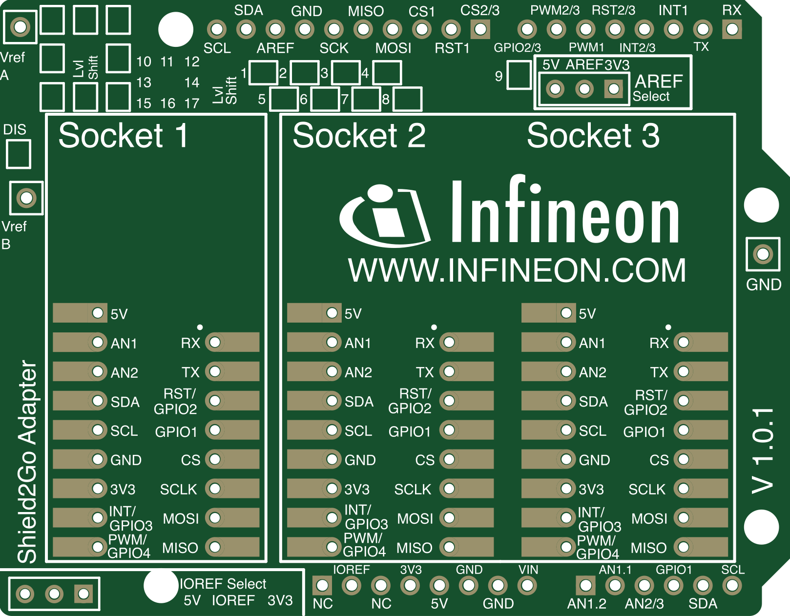
 Design with Infineon My IoT Adapter V1.0.1 in Cirkit Designer
Introduction
The Infineon My IoT Adapter V1.0.1 (Manufacturer Part ID: MYIOTADAPTERTOBO1) is a versatile IoT adapter designed to simplify the integration of IoT devices with cloud services. Developed by Infineon, this adapter supports multiple communication protocols, including Wi-Fi, Bluetooth, and Ethernet, making it an ideal choice for a wide range of IoT applications.
Explore Projects Built with Infineon My IoT Adapter V1.0.1
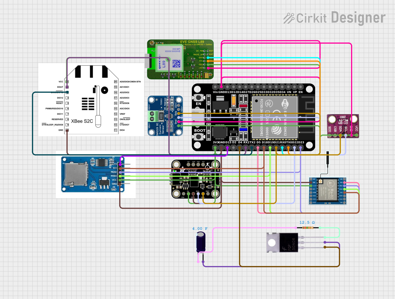 Open Project in Cirkit Designer
 Open Project in Cirkit Designer
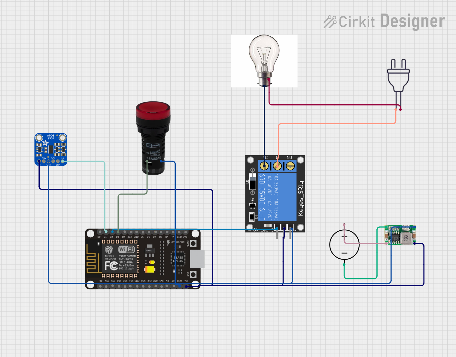 Open Project in Cirkit Designer
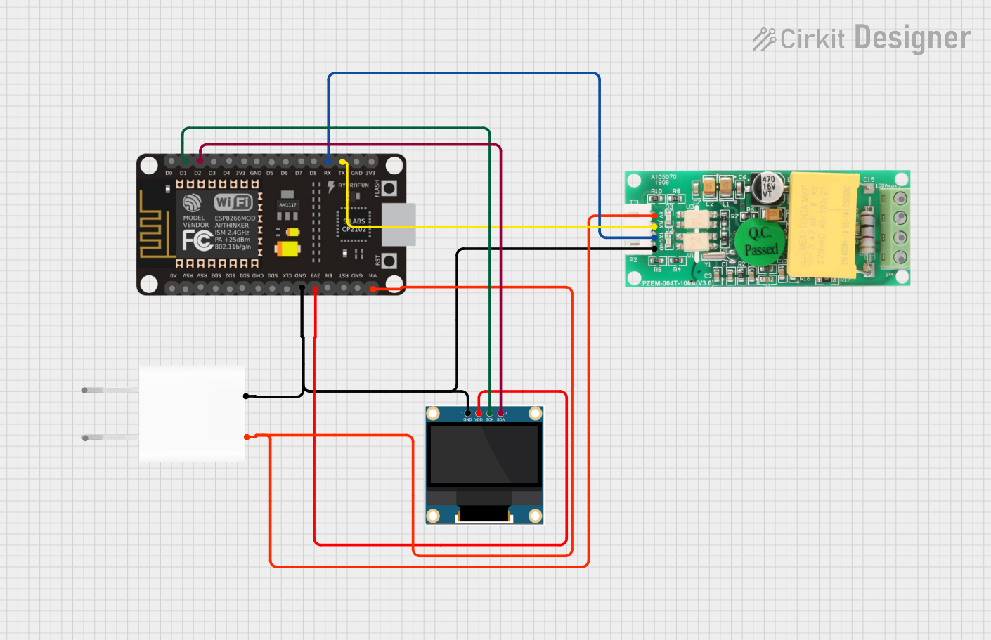 Open Project in Cirkit Designer
Explore Projects Built with Infineon My IoT Adapter V1.0.1
Open Project in Cirkit DesignerOpen Project in Cirkit DesignerOpen Project in Cirkit DesignerOpen Project in Cirkit DesignerCommon Applications and Use Cases
- Smart Home Automation: Seamlessly connect smart devices to cloud platforms for remote monitoring and control.
- Industrial IoT (IIoT): Enable secure and reliable communication between industrial sensors and cloud systems.
- Prototyping IoT Solutions: Rapidly develop and test IoT applications with its plug-and-play design.
- Edge Computing: Process and transmit data from edge devices to cloud services efficiently.
Technical Specifications
Key Technical Details
| Parameter | Value |
|---|---|
| Manufacturer | Infineon |
| Part ID | MYIOTADAPTERTOBO1 |
| Supported Protocols | Wi-Fi (802.11 b/g/n), Bluetooth 5.0, Ethernet |
| Operating Voltage | 3.3V to 5V |
| Power Consumption | 200mA (typical) |
| Operating Temperature | -20°C to +70°C |
| Dimensions | 50mm x 30mm x 10mm |
| Cloud Compatibility | AWS IoT, Microsoft Azure IoT, Google Cloud IoT, and others |
| Interface Options | UART, SPI, I2C, GPIO |
| Firmware Update | Over-the-Air (OTA) and USB |
Pin Configuration and Descriptions
| Pin Number | Pin Name | Description |
|---|---|---|
| 1 | VCC | Power supply input (3.3V to 5V) |
| 2 | GND | Ground connection |
| 3 | TX | UART Transmit pin for serial communication |
| 4 | RX | UART Receive pin for serial communication |
| 5 | SCL | I2C Clock Line |
| 6 | SDA | I2C Data Line |
| 7 | MOSI | SPI Master Out Slave In |
| 8 | MISO | SPI Master In Slave Out |
| 9 | SCK | SPI Clock |
| 10 | GPIO1 | General Purpose Input/Output pin 1 |
| 11 | GPIO2 | General Purpose Input/Output pin 2 |
| 12 | RESET | Reset pin to restart the adapter |
Usage Instructions
How to Use the Component in a Circuit
- Power Supply: Connect the VCC pin to a 3.3V or 5V power source and the GND pin to ground.
- Communication Interface: Choose the appropriate communication protocol (UART, SPI, or I2C) based on your application:
- For UART, connect the TX and RX pins to the corresponding pins on your microcontroller.
- For I2C, connect the SCL and SDA pins to the I2C bus.
- For SPI, connect the MOSI, MISO, and SCK pins to the SPI bus.
- GPIO Usage: Use the GPIO1 and GPIO2 pins for custom input/output operations.
- Cloud Integration: Configure the adapter to connect to your preferred cloud platform using the provided firmware tools or APIs.
Important Considerations and Best Practices
- Ensure the power supply voltage is within the specified range (3.3V to 5V) to avoid damaging the adapter.
- Use proper pull-up resistors for I2C communication if required by your circuit.
- Keep the firmware updated using the OTA or USB update feature to ensure compatibility with the latest cloud services.
- Avoid placing the adapter near high-frequency noise sources to maintain reliable communication.
Example: Connecting to an Arduino UNO
Below is an example of how to connect the Infineon My IoT Adapter to an Arduino UNO using UART communication:
Circuit Connections
- VCC → 5V on Arduino
- GND → GND on Arduino
- TX → Pin 10 on Arduino
- RX → Pin 11 on Arduino
Arduino Code Example
#include <SoftwareSerial.h>

// Define RX and TX pins for SoftwareSerial
SoftwareSerial myIoTAdapter(10, 11); // RX, TX

void setup() {
  // Initialize serial communication with the adapter
  myIoTAdapter.begin(9600);
  Serial.begin(9600); // For debugging via Serial Monitor

  // Send initialization command to the adapter
  myIoTAdapter.println("AT+CONNECT");
  Serial.println("Sent connection command to IoT adapter.");
}

void loop() {
  // Check for incoming data from the adapter
  if (myIoTAdapter.available()) {
    String data = myIoTAdapter.readString();
    Serial.println("Received from IoT adapter: " + data);
  }

  // Example: Send data to the adapter
  if (Serial.available()) {
    String command = Serial.readString();
    myIoTAdapter.println(command);
    Serial.println("Sent to IoT adapter: " + command);
  }
}
Troubleshooting and FAQs
Common Issues and Solutions
Adapter Not Powering On
- Cause: Insufficient or incorrect power supply.
- Solution: Verify that the VCC pin is connected to a 3.3V or 5V source and the GND pin is properly grounded.
No Communication with Microcontroller
- Cause: Incorrect pin connections or mismatched baud rate.
- Solution: Double-check the connections and ensure the baud rate in your code matches the adapter's default baud rate (9600).
Cloud Connection Fails
- Cause: Incorrect network credentials or unsupported cloud platform.
- Solution: Verify the Wi-Fi credentials and ensure the cloud platform is supported by the adapter.
Firmware Update Fails
- Cause: Interrupted update process or incompatible firmware file.
- Solution: Ensure a stable power supply during the update and use the correct firmware file provided by Infineon.
FAQs
Q: Can the adapter operate on battery power?
- A: Yes, as long as the battery provides a stable voltage between 3.3V and 5V.
Q: Does the adapter support MQTT protocol?
- A: Yes, the adapter supports MQTT for cloud communication.
Q: How do I reset the adapter?
- A: Connect the RESET pin to ground momentarily to perform a hardware reset.
Q: Can I use multiple adapters in the same network?
- A: Yes, but ensure each adapter has a unique identifier to avoid conflicts.
This concludes the documentation for the Infineon My IoT Adapter V1.0.1. For further assistance, refer to the official Infineon support resources.