
How to Use DS1302: Examples, Pinouts, and Specs
 Design with DS1302 in Cirkit Designer
Introduction
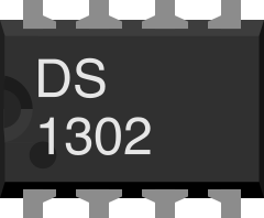
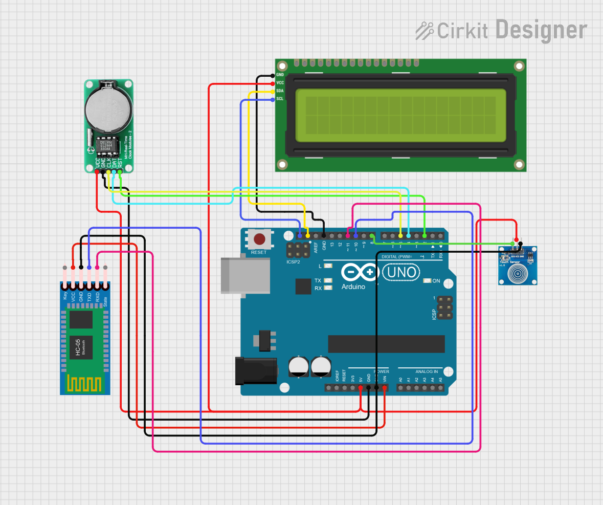
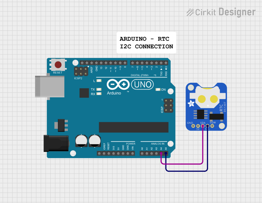
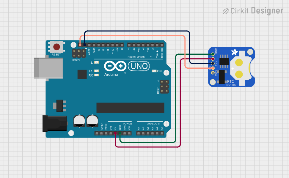
The DS1302 is a real-time clock (RTC) chip designed to keep track of the current time and date, including seconds, minutes, hours, day, date, month, and year. It features a serial interface for communication with microcontrollers and includes a battery backup capability, ensuring that the timekeeping function continues even during power outages. The DS1302 is widely used in applications requiring accurate timekeeping, such as data loggers, alarm systems, and embedded systems.
Explore Projects Built with DS1302
 Open Project in Cirkit Designer
 Open Project in Cirkit Designer
 Open Project in Cirkit Designer
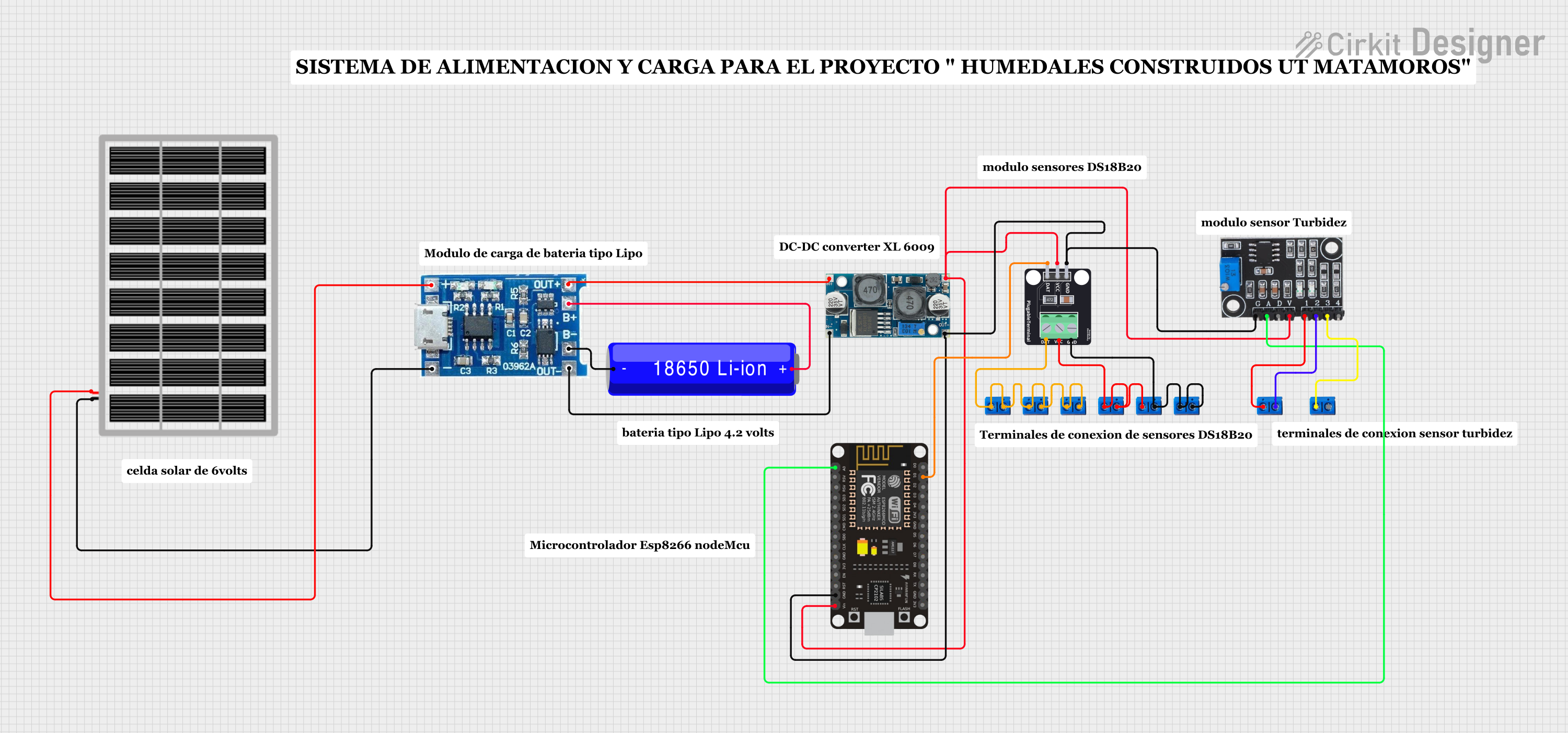 Open Project in Cirkit Designer
Explore Projects Built with DS1302
Open Project in Cirkit DesignerOpen Project in Cirkit DesignerOpen Project in Cirkit DesignerOpen Project in Cirkit DesignerCommon Applications:
- Digital clocks and timers
- Data logging systems
- Alarm systems
- Home automation
- Embedded systems requiring time and date tracking
Technical Specifications
The DS1302 is a low-power RTC chip with the following key specifications:
| Parameter | Value |
|---|---|
| Operating Voltage | 2.0V to 5.5V |
| Backup Battery Voltage | 2.0V to 3.5V |
| Operating Temperature | -40°C to +85°C |
| Communication Interface | Serial (3-wire: RST, I/O, SCLK) |
| Timekeeping Accuracy | ±2 minutes per month (at 25°C) |
| Current Consumption | 300nA (typical, with battery) |
| Clock Format | 12-hour or 24-hour mode |
| Memory | 31 bytes of user-accessible RAM |
Pin Configuration and Descriptions
The DS1302 comes in an 8-pin DIP or SOIC package. Below is the pinout and description:
| Pin | Name | Description |
|---|---|---|
| 1 | VCC1 | Primary power supply (2.0V to 5.5V). |
| 2 | X1 | Oscillator input. Connect to a 32.768 kHz crystal. |
| 3 | X2 | Oscillator output. Connect to a 32.768 kHz crystal. |
| 4 | GND | Ground. |
| 5 | RST | Reset pin. Used to enable communication with the chip. |
| 6 | I/O | Serial data input/output. |
| 7 | SCLK | Serial clock input. |
| 8 | VCC2 | Backup battery input (2.0V to 3.5V). |
Usage Instructions
Connecting the DS1302 to a Microcontroller
To use the DS1302 in a circuit, follow these steps:
- Connect the VCC1 pin to the primary power supply (e.g., 5V for most microcontrollers).
- Connect the GND pin to the ground of the circuit.
- Attach a 32.768 kHz crystal oscillator between the X1 and X2 pins.
- Connect the RST, I/O, and SCLK pins to the corresponding GPIO pins on your microcontroller.
- Optionally, connect a backup battery (e.g., a 3V coin cell) to the VCC2 pin to maintain timekeeping during power loss.
Important Considerations:
- Use decoupling capacitors (e.g., 0.1 µF) near the power supply pins to reduce noise.
- Ensure the crystal oscillator is of high quality and matches the required frequency (32.768 kHz).
- Avoid long wires for the crystal connections to minimize interference.
- Use pull-up resistors on the I/O line if required by your microcontroller.
Example: Using DS1302 with Arduino UNO
Below is an example Arduino sketch to interface with the DS1302 and set/read the time:
#include <DS1302.h> // Include the DS1302 library

// Define DS1302 pins
#define RST_PIN 7   // Reset pin connected to Arduino pin 7
#define IO_PIN 6    // I/O pin connected to Arduino pin 6
#define SCLK_PIN 5  // Serial clock pin connected to Arduino pin 5

// Create an instance of the DS1302 class
DS1302 rtc(RST_PIN, IO_PIN, SCLK_PIN);

void setup() {
  Serial.begin(9600); // Initialize serial communication
  rtc.halt(false);    // Start the RTC
  rtc.writeProtect(false); // Disable write protection

  // Set the date and time (Year, Month, Day, Hour, Minute, Second)
  rtc.setDateTime(2023, 10, 15, 14, 30, 0); // Example: 15th Oct 2023, 14:30:00
}

void loop() {
  // Read the current date and time
  DS1302::DateTime now = rtc.getDateTime();

  // Print the date and time to the Serial Monitor
  Serial.print("Date: ");
  Serial.print(now.year);
  Serial.print("-");
  Serial.print(now.month);
  Serial.print("-");
  Serial.println(now.day);

  Serial.print("Time: ");
  Serial.print(now.hour);
  Serial.print(":");
  Serial.print(now.minute);
  Serial.print(":");
  Serial.println(now.second);

  delay(1000); // Wait for 1 second before updating
}
Notes:
- Install the DS1302 library in your Arduino IDE before running the code.
- Modify the pin definitions if you are using different GPIO pins.
Troubleshooting and FAQs
Common Issues:
RTC not keeping time when power is off:
- Ensure the backup battery is properly connected to the VCC2 pin.
- Verify that the battery voltage is within the acceptable range (2.0V to 3.5V).
Incorrect time or date:
- Check the crystal oscillator connections for stability and proper frequency.
- Ensure the time and date are set correctly in the code.
No communication with the microcontroller:
- Verify the connections for the RST, I/O, and SCLK pins.
- Ensure the microcontroller pins are configured correctly in the code.
Time drifts over long periods:
- Use a high-quality crystal oscillator with low temperature drift.
- Minimize electrical noise in the circuit.
FAQs:
Q: Can the DS1302 operate without a backup battery?
A: Yes, but it will lose the time and date settings when the primary power supply is disconnected.
Q: What is the difference between VCC1 and VCC2?
A: VCC1 is the primary power supply, while VCC2 is for the backup battery. The chip automatically switches to VCC2 when VCC1 is unavailable.
Q: Can I use the DS1302 with a 3.3V microcontroller?
A: Yes, the DS1302 operates within a voltage range of 2.0V to 5.5V, making it compatible with 3.3V systems.
Q: How much memory is available for user data?
A: The DS1302 provides 31 bytes of user-accessible RAM for storing custom data.
By following this documentation, you can effectively integrate the DS1302 into your projects for reliable timekeeping functionality.