How to Use BLUE LED: Examples, Pinouts, and Specs

Introduction
A blue light-emitting diode (LED) is a semiconductor device that emits blue light when an electric current flows through it. Blue LEDs are widely used in various applications due to their efficiency, durability, and vibrant color. They are commonly found in indicator lights, displays, decorative lighting, and even in high-power applications like automotive lighting and flashlights.
Explore Projects Built with BLUE LED
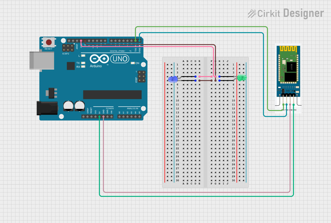
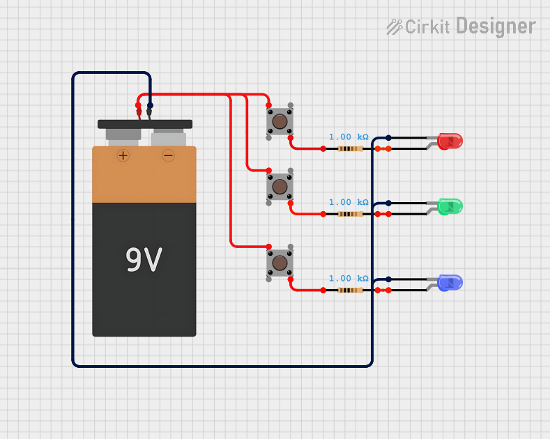
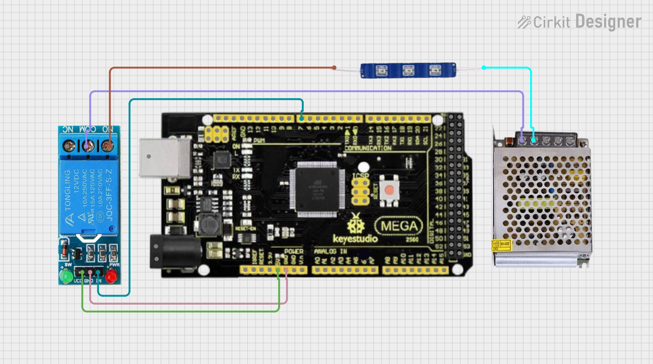
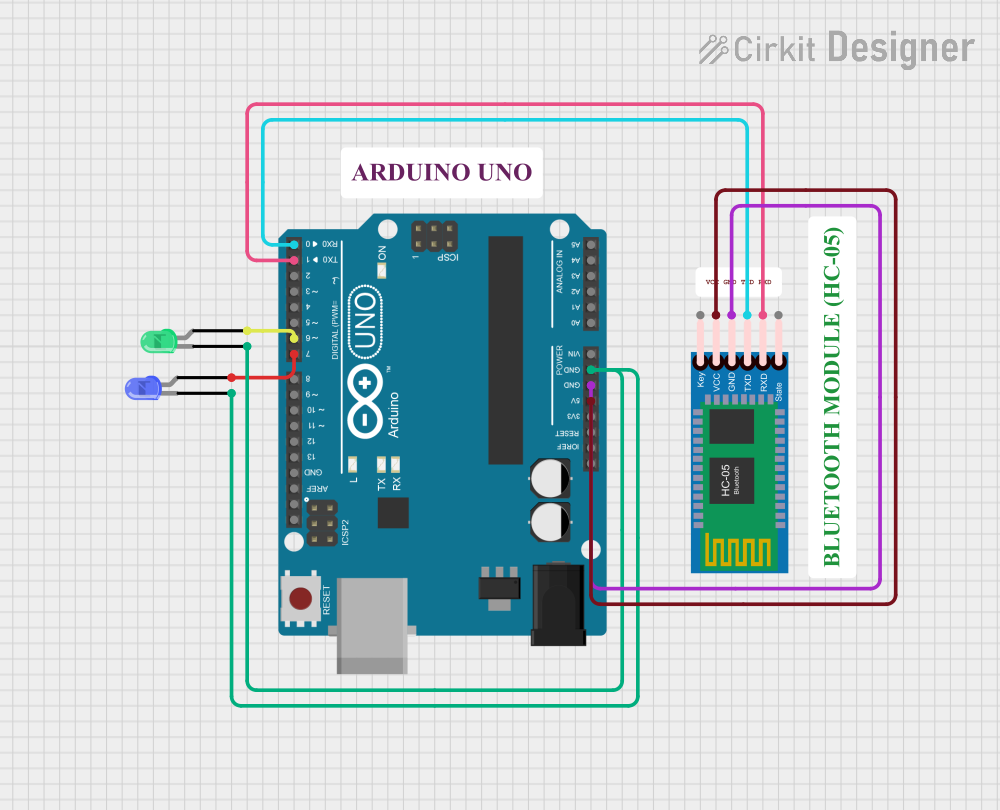
Explore Projects Built with BLUE LED
Technical Specifications
Below are the key technical details for a standard blue LED:
| Parameter | Value |
|---|---|
| Forward Voltage (Vf) | 2.8V to 3.6V |
| Forward Current (If) | 20mA (typical) |
| Maximum Current (Imax) | 30mA |
| Wavelength | 450nm to 495nm |
| Viewing Angle | 20° to 60° (varies by model) |
| Power Dissipation | 75mW (typical) |
| Reverse Voltage (Vr) | 5V (maximum) |
| Operating Temperature | -40°C to +85°C |
Pin Configuration and Descriptions
A blue LED typically has two pins:
| Pin | Description |
|---|---|
| Anode (+) | The longer pin, connected to the positive terminal of the power supply or circuit. |
| Cathode (-) | The shorter pin, connected to the negative terminal or ground. |
Note: If the pins are trimmed or unclear, the flat edge on the LED casing indicates the cathode.
Usage Instructions
How to Use the Blue LED in a Circuit
Determine the Resistor Value:
To prevent damage to the LED, a current-limiting resistor must be used. Calculate the resistor value using Ohm's Law:
[ R = \frac{V_{supply} - V_f}{I_f} ]
Where:- ( V_{supply} ) is the supply voltage.
- ( V_f ) is the forward voltage of the LED (e.g., 3.2V).
- ( I_f ) is the forward current (e.g., 20mA or 0.02A).
For example, with a 5V supply and a forward voltage of 3.2V:
[ R = \frac{5V - 3.2V}{0.02A} = 90\Omega ]
Use the nearest standard resistor value (e.g., 100Ω).Connect the LED:
- Connect the anode (+) to the positive terminal of the power supply through the resistor.
- Connect the cathode (-) to the ground.
Test the Circuit:
Power the circuit and observe the blue light emitted by the LED. If it does not light up, check the polarity and connections.
Important Considerations and Best Practices
- Polarity Matters: LEDs are polarized components. Reversing the polarity may prevent the LED from lighting up or cause damage.
- Avoid Overcurrent: Exceeding the maximum current rating can permanently damage the LED. Always use a current-limiting resistor.
- Heat Management: In high-power applications, ensure proper heat dissipation to avoid thermal damage.
- Series and Parallel Configurations: When using multiple LEDs, calculate resistor values for each configuration to ensure uniform brightness.
Example: Connecting a Blue LED to an Arduino UNO
Below is an example of how to connect and control a blue LED using an Arduino UNO:
Circuit Setup
- Connect the anode (+) of the LED to a 220Ω resistor, and then to digital pin 9 on the Arduino.
- Connect the cathode (-) of the LED to the Arduino's GND pin.
Code Example
// This code blinks a blue LED connected to pin 9 of the Arduino UNO.
// Ensure a 220Ω resistor is used to limit current through the LED.

const int ledPin = 9; // Pin connected to the LED

void setup() {
  pinMode(ledPin, OUTPUT); // Set pin 9 as an output
}

void loop() {
  digitalWrite(ledPin, HIGH); // Turn the LED on
  delay(1000);               // Wait for 1 second
  digitalWrite(ledPin, LOW);  // Turn the LED off
  delay(1000);               // Wait for 1 second
}
Tip: Adjust the
delay()values to change the blinking speed.
Troubleshooting and FAQs
Common Issues and Solutions
LED Does Not Light Up:
- Cause: Incorrect polarity or loose connections.
- Solution: Ensure the anode is connected to the positive terminal and the cathode to ground. Check all connections.
LED is Dim:
- Cause: Resistor value too high.
- Solution: Recalculate the resistor value to allow more current (but within safe limits).
LED Burns Out Quickly:
- Cause: Excessive current or voltage.
- Solution: Use a proper current-limiting resistor and ensure the supply voltage does not exceed the LED's ratings.
Flickering LED:
- Cause: Unstable power supply or loose connections.
- Solution: Check the power source and ensure all connections are secure.
FAQs
Q: Can I connect a blue LED directly to a 3.3V or 5V power supply?
A: No, always use a current-limiting resistor to prevent damage to the LED.Q: Why is my LED not as bright as expected?
A: Check the resistor value and ensure the supply voltage is sufficient for the LED's forward voltage.Q: Can I use a blue LED with a PWM signal?
A: Yes, blue LEDs work well with PWM (Pulse Width Modulation) for brightness control.Q: How do I connect multiple blue LEDs?
A: For series connections, sum the forward voltages and use a single resistor. For parallel connections, use individual resistors for each LED.
By following this documentation, you can effectively use a blue LED in your projects while ensuring optimal performance and longevity.