How to Use Opta Ext: Examples, Pinouts, and Specs
Introduction
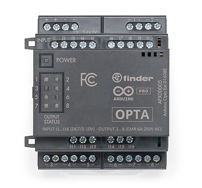
The Opta Ext (Manufacturer Part ID: D1608E) is a versatile extension module developed by Arduino. It is designed to enhance the capabilities of various electronic systems by providing additional input/output interfaces or functionalities. This module is particularly useful in industrial automation, IoT applications, and projects requiring expanded connectivity or control.
Explore Projects Built with Opta Ext

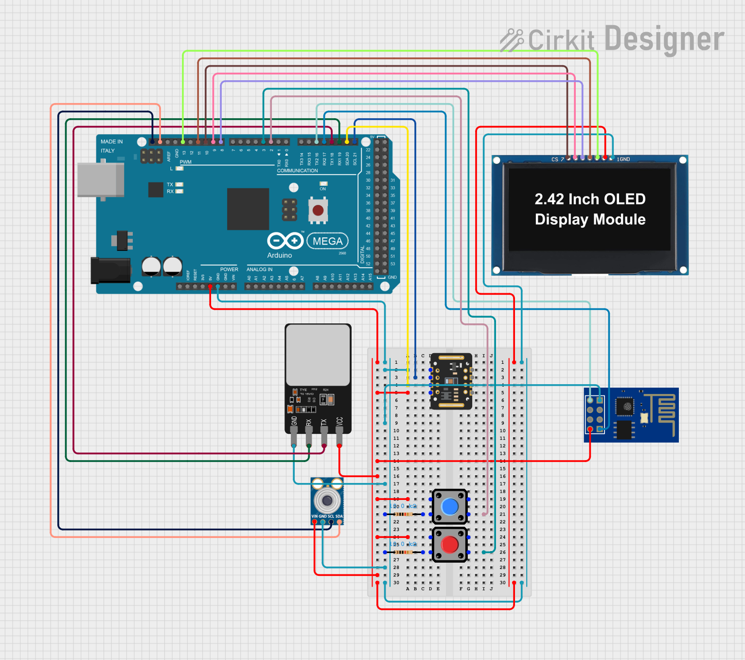
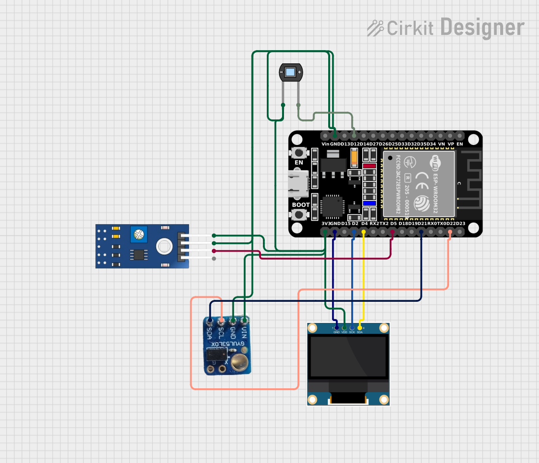

Explore Projects Built with Opta Ext
Common Applications and Use Cases
- Expanding the number of I/O ports in microcontroller-based systems.
- Adding functionality to industrial automation systems.
- Enhancing IoT devices with additional sensors or actuators.
- Prototyping and testing complex electronic systems.
Technical Specifications
The following table outlines the key technical details of the Opta Ext module:
| Parameter | Specification |
|---|---|
| Operating Voltage | 5V DC |
| Input Voltage Range | 4.5V to 5.5V |
| Maximum Current | 500mA |
| Communication Protocol | I2C, SPI, UART |
| Number of I/O Pins | 16 (configurable as input or output) |
| Dimensions | 50mm x 25mm x 10mm |
| Operating Temperature | -40°C to 85°C |
Pin Configuration and Descriptions
The Opta Ext module features a 16-pin interface. The pin configuration is as follows:
| Pin Number | Pin Name | Description |
|---|---|---|
| 1 | VCC | Power supply input (5V DC) |
| 2 | GND | Ground |
| 3 | SDA | I2C Data Line |
| 4 | SCL | I2C Clock Line |
| 5 | MOSI | SPI Master Out Slave In |
| 6 | MISO | SPI Master In Slave Out |
| 7 | SCK | SPI Clock |
| 8 | CS | SPI Chip Select |
| 9-16 | IO1-IO8 | Configurable Input/Output pins |
Usage Instructions
How to Use the Opta Ext in a Circuit
- Powering the Module: Connect the VCC pin to a 5V DC power source and the GND pin to the ground of your circuit.
- Communication Setup: Depending on your application, connect the appropriate communication lines (I2C, SPI, or UART) to your microcontroller or host device.
- Configuring I/O Pins: Use the provided library or firmware to configure the IO1-IO8 pins as either inputs or outputs.
- Connecting Peripherals: Attach sensors, actuators, or other peripherals to the I/O pins as needed.
Important Considerations and Best Practices
- Ensure the power supply voltage is within the specified range (4.5V to 5.5V) to avoid damage to the module.
- Use pull-up resistors for I2C communication lines (SDA and SCL) if not already provided in your circuit.
- Avoid exceeding the maximum current rating of 500mA to prevent overheating or damage.
- When using SPI, ensure the correct configuration of the Chip Select (CS) pin to avoid communication conflicts.
Example: Using Opta Ext with Arduino UNO
Below is an example of how to use the Opta Ext module with an Arduino UNO via I2C communication:
#include <Wire.h> // Include the Wire library for I2C communication

#define OPTA_EXT_I2C_ADDRESS 0x20 // Replace with the actual I2C address of Opta Ext

void setup() {
  Wire.begin(); // Initialize I2C communication
  Serial.begin(9600); // Start serial communication for debugging

  // Configure Opta Ext I/O pins (example: set IO1 as output)
  Wire.beginTransmission(OPTA_EXT_I2C_ADDRESS);
  Wire.write(0x01); // Command to configure IO1
  Wire.write(0x01); // Set IO1 as output
  Wire.endTransmission();

  Serial.println("Opta Ext initialized.");
}

void loop() {
  // Example: Toggle IO1 every second
  Wire.beginTransmission(OPTA_EXT_I2C_ADDRESS);
  Wire.write(0x02); // Command to write to IO1
  Wire.write(0x01); // Set IO1 HIGH
  Wire.endTransmission();
  delay(1000);

  Wire.beginTransmission(OPTA_EXT_I2C_ADDRESS);
  Wire.write(0x02); // Command to write to IO1
  Wire.write(0x00); // Set IO1 LOW
  Wire.endTransmission();
  delay(1000);
}
Troubleshooting and FAQs
Common Issues and Solutions
Module Not Responding
- Cause: Incorrect wiring or power supply issues.
- Solution: Double-check all connections and ensure the power supply voltage is within the specified range.
I2C Communication Fails
- Cause: Missing pull-up resistors or incorrect I2C address.
- Solution: Add pull-up resistors (4.7kΩ recommended) to the SDA and SCL lines. Verify the I2C address of the module.
Overheating
- Cause: Exceeding the maximum current rating.
- Solution: Ensure the total current drawn by connected peripherals does not exceed 500mA.
Unexpected Behavior of I/O Pins
- Cause: Incorrect configuration of I/O pins.
- Solution: Verify the pin configuration commands in your code and ensure they match your intended setup.
FAQs
Q: Can the Opta Ext be used with 3.3V systems?
A: No, the Opta Ext requires a 5V power supply. Use a level shifter if interfacing with 3.3V systems.Q: How many Opta Ext modules can be connected to a single microcontroller?
A: This depends on the communication protocol. For I2C, up to 127 devices can be connected, provided each has a unique address.Q: Is there a library available for the Opta Ext?
A: Yes, Arduino provides a library for the Opta Ext module. Check the official Arduino website for the latest version.
This concludes the documentation for the Opta Ext module. For further assistance, refer to the official Arduino support resources.