
How to Use Header 6: Examples, Pinouts, and Specs
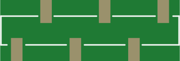
 Design with Header 6 in Cirkit Designer
Introduction
A Header 6 is a type of connector used in electronic circuits, typically featuring six pins arranged in a single or dual row. It is designed to facilitate the connection of various components or devices, enabling easy assembly, disassembly, and prototyping. Header 6 connectors are widely used in breadboards, microcontroller boards, and other electronic systems where modularity and flexibility are required.
Explore Projects Built with Header 6
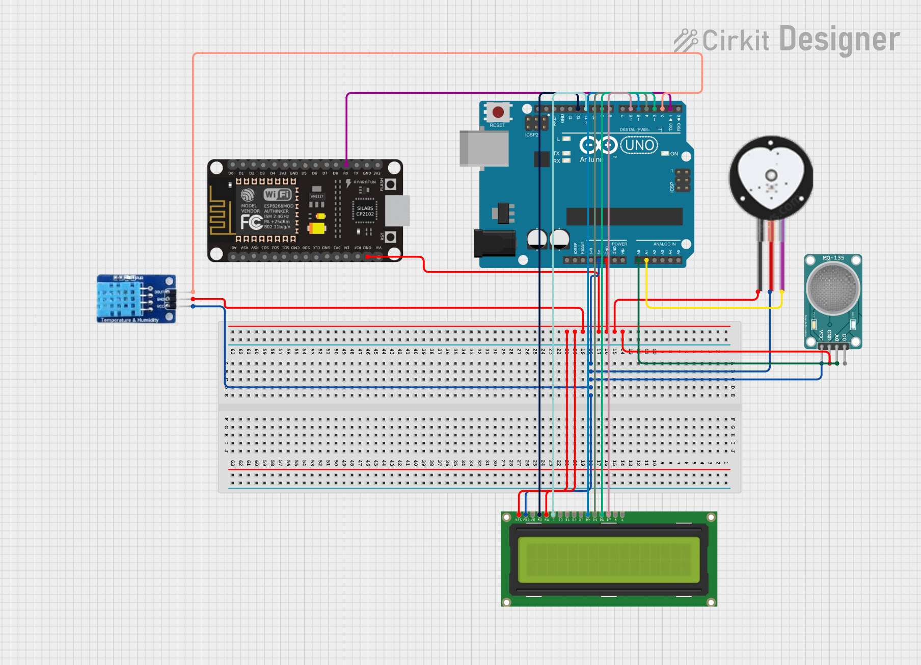 Open Project in Cirkit Designer
 Open Project in Cirkit Designer
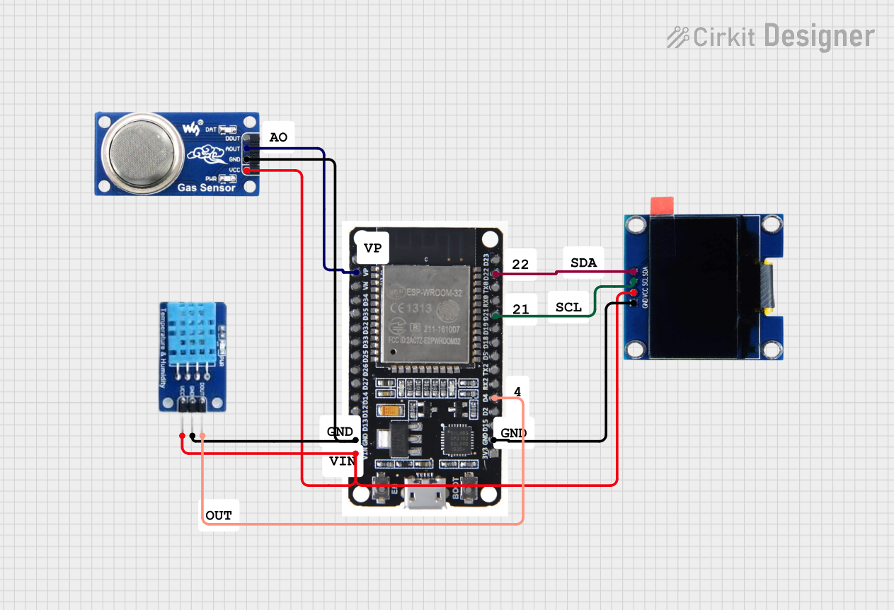 Open Project in Cirkit Designer
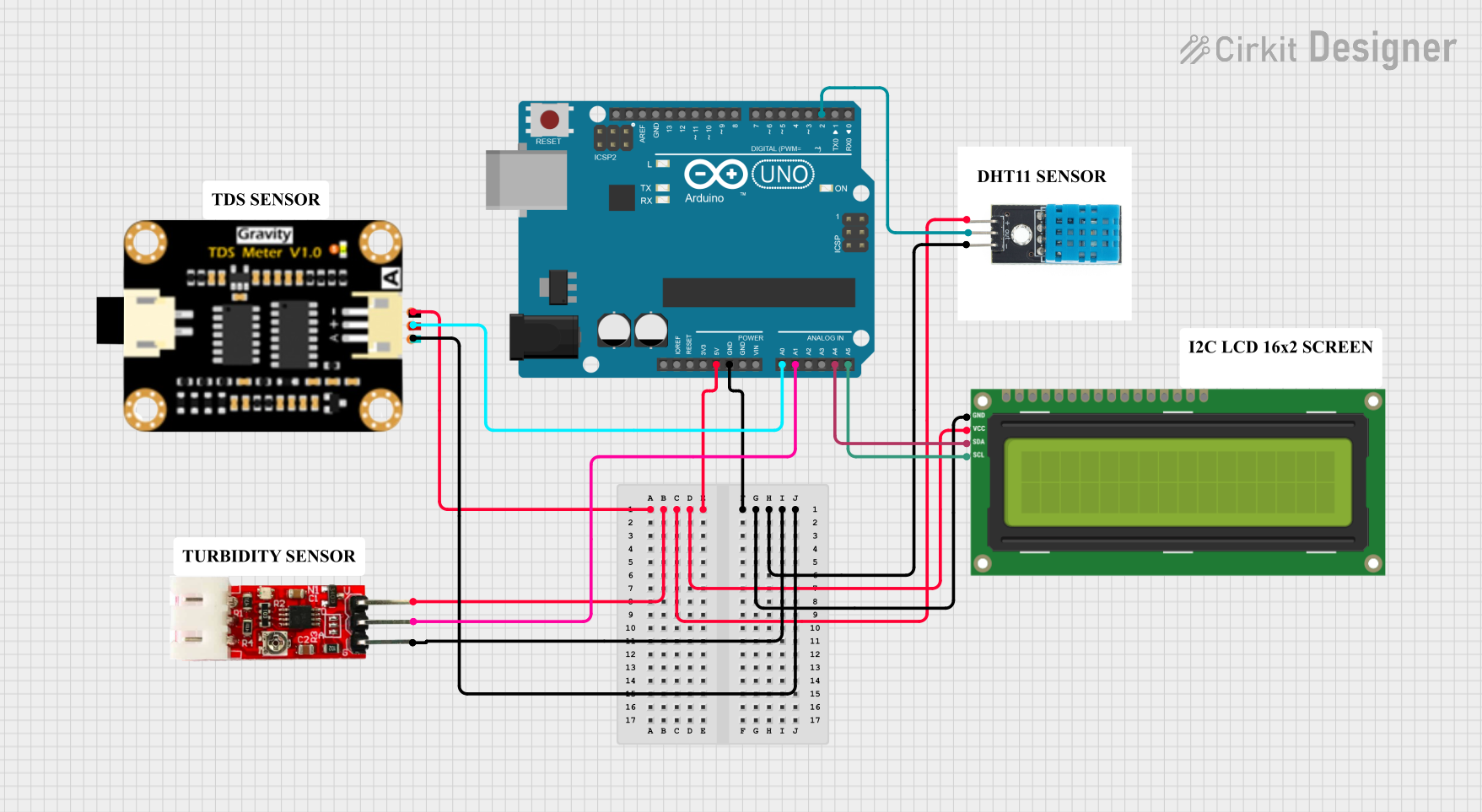 Open Project in Cirkit Designer
Explore Projects Built with Header 6
Open Project in Cirkit DesignerOpen Project in Cirkit DesignerOpen Project in Cirkit DesignerOpen Project in Cirkit DesignerCommon Applications and Use Cases
- Connecting sensors, modules, or peripherals to microcontroller boards (e.g., Arduino, Raspberry Pi).
- Prototyping circuits on breadboards.
- Establishing connections between PCBs (Printed Circuit Boards).
- Creating modular designs for easy maintenance and upgrades.
Technical Specifications
Key Technical Details
- Number of Pins: 6
- Pin Pitch: 2.54 mm (standard spacing)
- Current Rating: Typically 1A per pin (varies by manufacturer)
- Voltage Rating: Up to 250V (varies by manufacturer)
- Material:
- Pins: Tin-plated or gold-plated copper alloy.
- Housing: Thermoplastic or similar insulating material.
- Temperature Range: -40°C to 105°C (varies by manufacturer)
- Mounting Type: Through-hole or surface-mount.
Pin Configuration and Descriptions
The Header 6 connector consists of six pins, which can be used for various purposes depending on the circuit design. Below is a general description of the pin configuration:
| Pin Number | Description | Notes |
|---|---|---|
| 1 | Power (VCC) | Supplies power to the connected device. |
| 2 | Ground (GND) | Common ground for the circuit. |
| 3 | Signal/Data Line 1 | Used for transmitting or receiving signals. |
| 4 | Signal/Data Line 2 | Used for transmitting or receiving signals. |
| 5 | Signal/Data Line 3 | Used for transmitting or receiving signals. |
| 6 | Signal/Data Line 4 | Used for transmitting or receiving signals. |
Note: The specific pin assignments may vary depending on the application or device. Always refer to the datasheet or schematic for your specific use case.
Usage Instructions
How to Use the Header 6 in a Circuit
- Identify the Pinout: Refer to the datasheet or schematic to determine the function of each pin.
- Soldering:
- For through-hole headers, insert the pins into the PCB holes and solder them securely.
- For surface-mount headers, align the pins with the PCB pads and solder carefully.
- Connecting Components: Use jumper wires, ribbon cables, or compatible connectors to link the Header 6 to other components or devices.
- Ensure Proper Orientation: Double-check the orientation of the header to avoid incorrect connections.
Important Considerations and Best Practices
- Avoid Overcurrent: Do not exceed the current rating of the pins to prevent overheating or damage.
- Secure Connections: Ensure that the header is firmly soldered to the PCB and that connected wires or cables are not loose.
- Use Proper Tools: When soldering, use a temperature-controlled soldering iron to avoid damaging the header or PCB.
- Check Compatibility: Verify that the pin pitch (2.54 mm) matches the mating connector or PCB layout.
Example: Connecting a Header 6 to an Arduino UNO
The Header 6 can be used to connect peripherals like sensors or modules to an Arduino UNO. Below is an example of connecting a sensor with a Header 6 to the Arduino:
Circuit Diagram
- Pin 1 (VCC) → Arduino 5V
- Pin 2 (GND) → Arduino GND
- Pin 3 (Signal) → Arduino Digital Pin 2
Arduino Code Example
// Example code for reading a digital signal from a sensor connected via Header 6

const int sensorPin = 2; // Pin 3 of Header 6 connected to Arduino Digital Pin 2
int sensorValue = 0;     // Variable to store the sensor reading

void setup() {
  pinMode(sensorPin, INPUT); // Set the sensor pin as an input
  Serial.begin(9600);        // Initialize serial communication
}

void loop() {
  sensorValue = digitalRead(sensorPin); // Read the sensor value
  Serial.print("Sensor Value: ");       // Print the sensor value to the Serial Monitor
  Serial.println(sensorValue);
  delay(500); // Wait for 500ms before reading again
}
Note: Modify the code and connections as needed for your specific sensor or module.
Troubleshooting and FAQs
Common Issues and Solutions
Loose Connections:
- Issue: The circuit is not functioning properly due to intermittent connections.
- Solution: Ensure that the header is securely soldered to the PCB and that all wires or connectors are firmly attached.
Incorrect Pinout:
- Issue: The device does not work because the pins are connected incorrectly.
- Solution: Double-check the pinout and ensure that each pin is connected to the correct signal or power source.
Overheating:
- Issue: The header or connected components become hot during operation.
- Solution: Verify that the current and voltage ratings are not being exceeded.
Signal Interference:
- Issue: Data transmission is unreliable due to noise or interference.
- Solution: Use shorter wires, shielded cables, or add pull-up/pull-down resistors as needed.
FAQs
Q: Can I use a Header 6 for high-frequency signals?
- A: Yes, but ensure that the signal integrity is maintained by using proper PCB design practices and minimizing noise.
Q: Are Header 6 connectors reusable?
- A: Yes, they can be reused, but repeated soldering and desoldering may degrade the pins over time.
Q: Can I use a Header 6 with a breadboard?
- A: Yes, the 2.54 mm pin pitch is compatible with standard breadboards.
Q: What tools do I need to solder a Header 6?
- A: A soldering iron, solder wire, and flux are typically required. A desoldering pump or wick may also be useful for corrections.
By following this documentation, you can effectively use a Header 6 connector in your electronic projects.