How to Use vibration shock sensor 801s: Examples, Pinouts, and Specs
Introduction
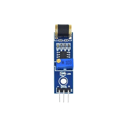
The Vibration Shock Sensor 801S is a compact and reliable sensor designed to detect vibrations and shocks. It is commonly used in security systems, industrial monitoring, and other applications where detecting physical disturbances is critical. The sensor operates by generating a signal when it detects a vibration or shock, making it ideal for triggering alarms, logging events, or controlling other devices in a system.
Explore Projects Built with vibration shock sensor 801s
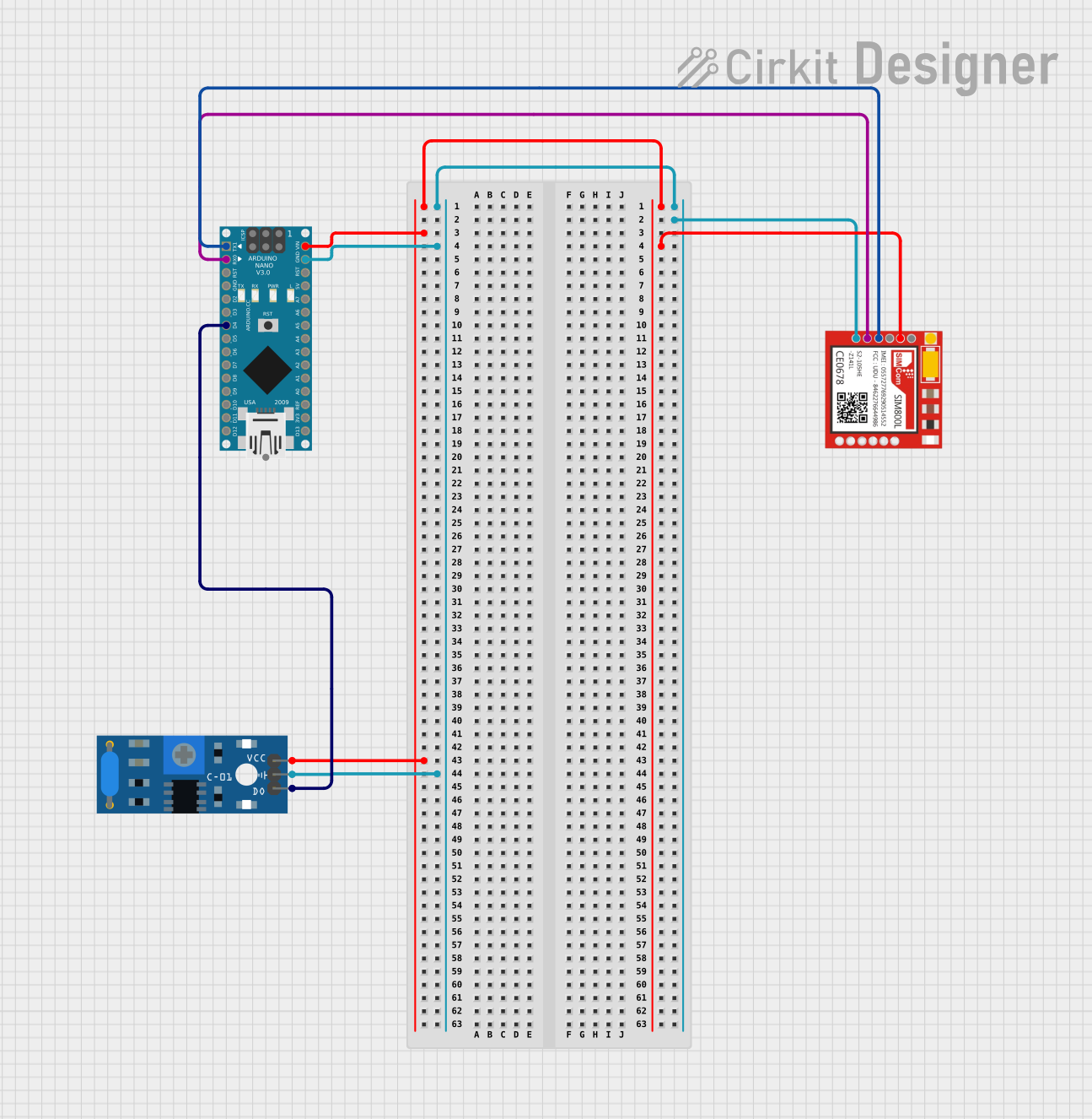
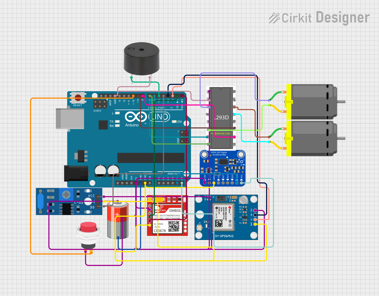


Explore Projects Built with vibration shock sensor 801s
Common Applications
- Security systems to detect unauthorized access or tampering
- Industrial equipment monitoring for abnormal vibrations
- Smart home systems for detecting movement or impacts
- Automotive systems for collision or impact detection
- Robotics and automation for environmental feedback
Technical Specifications
The following table outlines the key technical details of the Vibration Shock Sensor 801S:
| Parameter | Value |
|---|---|
| Operating Voltage | 3.3V to 5V |
| Output Signal | Digital (High/Low) |
| Sensitivity | Adjustable (via external circuit) |
| Operating Temperature | -20°C to 70°C |
| Dimensions | 10mm x 10mm x 35mm |
| Response Time | < 1ms |
| Power Consumption | Low |
Pin Configuration
The Vibration Shock Sensor 801S typically has three pins. The table below describes each pin:
| Pin | Name | Description |
|---|---|---|
| 1 | VCC | Power supply pin (3.3V to 5V) |
| 2 | GND | Ground connection |
| 3 | OUT | Digital output pin (High when vibration is detected) |
Usage Instructions
How to Use the Sensor in a Circuit
- Power the Sensor: Connect the
VCCpin to a 3.3V or 5V power source and theGNDpin to the ground of your circuit. - Connect the Output: Attach the
OUTpin to a microcontroller's digital input pin or another device that can process the sensor's output signal. - Read the Signal: When the sensor detects a vibration or shock, the
OUTpin will output a HIGH signal. Otherwise, it will remain LOW. - Adjust Sensitivity: If the sensor's sensitivity is adjustable (depending on the module), use the onboard potentiometer or external circuit to fine-tune the detection threshold.
Important Considerations
- Debouncing: The sensor may produce multiple signals for a single vibration. Use software debouncing techniques to filter out noise.
- Mounting: Secure the sensor firmly to avoid false triggers caused by unintended movements.
- Power Supply: Ensure a stable power supply to avoid erratic behavior.
- Environmental Factors: Avoid exposing the sensor to extreme temperatures or moisture, as this may affect its performance.
Example: Connecting to an Arduino UNO
Below is an example of how to connect and use the Vibration Shock Sensor 801S with an Arduino UNO:
Circuit Diagram
- Connect the
VCCpin of the sensor to the 5V pin on the Arduino. - Connect the
GNDpin of the sensor to the GND pin on the Arduino. - Connect the
OUTpin of the sensor to digital pin 2 on the Arduino.
Arduino Code
// Vibration Shock Sensor 801S Example Code
// This code reads the sensor's output and prints a message when vibration is detected.

const int sensorPin = 2; // Pin connected to the sensor's OUT pin
const int ledPin = 13;   // Built-in LED pin for visual feedback

void setup() {
  pinMode(sensorPin, INPUT); // Set sensor pin as input
  pinMode(ledPin, OUTPUT);   // Set LED pin as output
  Serial.begin(9600);        // Initialize serial communication
}

void loop() {
  int sensorValue = digitalRead(sensorPin); // Read the sensor's output

  if (sensorValue == HIGH) {
    // Vibration detected
    Serial.println("Vibration detected!");
    digitalWrite(ledPin, HIGH); // Turn on LED
    delay(500);                 // Wait for 500ms
  } else {
    // No vibration
    digitalWrite(ledPin, LOW);  // Turn off LED
  }
}
Notes on the Code
- The built-in LED on the Arduino UNO (pin 13) is used to provide visual feedback when a vibration is detected.
- The
delay(500)function ensures that the LED stays on for 500ms after a vibration is detected, which also helps reduce false triggers.
Troubleshooting and FAQs
Common Issues
Sensor Not Responding
- Cause: Incorrect wiring or insufficient power supply.
- Solution: Double-check the connections and ensure the power supply is within the specified range (3.3V to 5V).
False Triggers
- Cause: Environmental noise or improper mounting.
- Solution: Secure the sensor firmly and use software debouncing to filter out noise.
No Output Signal
- Cause: Faulty sensor or damaged components.
- Solution: Test the sensor with a multimeter or replace it if necessary.
Interference with Other Components
- Cause: Shared power supply or improper grounding.
- Solution: Use a separate power supply or ensure proper grounding for all components.
FAQs
Q: Can the sensor detect continuous vibrations?
A: The sensor is designed to detect discrete shocks or vibrations. For continuous vibration monitoring, additional signal processing may be required.
Q: Is the sensor waterproof?
A: No, the Vibration Shock Sensor 801S is not waterproof. Avoid exposing it to moisture or liquids.
Q: Can I use this sensor with a 3.3V microcontroller?
A: Yes, the sensor operates within a voltage range of 3.3V to 5V, making it compatible with 3.3V microcontrollers like the ESP32.
Q: How do I adjust the sensitivity?
A: If your module includes a potentiometer, turn it clockwise or counterclockwise to increase or decrease sensitivity. For modules without a potentiometer, sensitivity adjustments may require external circuitry.
By following this documentation, you can effectively integrate the Vibration Shock Sensor 801S into your projects and troubleshoot common issues with ease.