How to Use MMA8451Q: Examples, Pinouts, and Specs

 Design with MMA8451Q in Cirkit Designer
Introduction
The MMA8451Q is a low-power, three-axis accelerometer with a digital output, manufactured by NXP Semiconductors. It is designed for motion sensing applications, providing precise acceleration data along the X, Y, and Z axes. The device supports a wide range of features, including a built-in FIFO buffer, configurable full-scale ranges (±2g, ±4g, ±8g), and multiple power modes to balance performance and energy efficiency.
Explore Projects Built with MMA8451Q

 Open Project in Cirkit Designer
 Open Project in Cirkit Designer
 Open Project in Cirkit Designer
 Open Project in Cirkit Designer
Explore Projects Built with MMA8451Q

 Open Project in Cirkit Designer
 Open Project in Cirkit Designer
 Open Project in Cirkit Designer
 Open Project in Cirkit Designer
Common Applications
- Motion detection and gesture recognition
- Tilt sensing and orientation detection
- Free-fall detection for device protection
- Activity monitoring in wearable devices
- Gaming and augmented reality applications
Technical Specifications
The following table outlines the key technical details of the MMA8451Q:
| Parameter | Value |
|---|---|
| Supply Voltage (VDD) | 1.95V to 3.6V |
| I/O Voltage (VDDIO) | 1.6V to 3.6V |
| Operating Current | 165 µA (Active Mode) |
| Standby Current | 1 µA |
| Output Interface | I²C (up to 400 kHz) |
| Measurement Range | ±2g, ±4g, ±8g (configurable) |
| Resolution | 14-bit |
| FIFO Buffer Size | 32 samples |
| Operating Temperature Range | -40°C to +85°C |
| Package Type | QFN-16 (3 mm x 3 mm x 1 mm) |
Pin Configuration
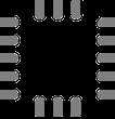
The MMA8451Q is available in a 16-pin QFN package. The pinout and descriptions are as follows:
| Pin Number | Pin Name | Description |
|---|---|---|
| 1 | VDD | Power supply (1.95V to 3.6V) |
| 2 | VDDIO | I/O voltage supply (1.6V to 3.6V) |
| 3 | GND | Ground |
| 4 | SCL | I²C clock line |
| 5 | SDA | I²C data line |
| 6 | INT1 | Interrupt 1 output |
| 7 | INT2 | Interrupt 2 output |
| 8-16 | NC | No connection (leave unconnected or grounded) |
Usage Instructions
Connecting the MMA8451Q to a Circuit
- Power Supply: Connect the VDD pin to a 3.3V power source and the GND pin to ground. If your microcontroller operates at 5V logic, use a level shifter for the I²C lines.
- I²C Interface: Connect the SCL and SDA pins to the corresponding I²C pins on your microcontroller. Pull-up resistors (typically 4.7 kΩ) are required on both lines.
- Interrupts (Optional): Connect INT1 and/or INT2 to GPIO pins on your microcontroller if you plan to use interrupt-driven features.
Example Code for Arduino UNO
Below is an example of how to interface the MMA8451Q with an Arduino UNO using the Adafruit MMA8451 library:
#include <Wire.h>
#include <Adafruit_MMA8451.h>
#include <Adafruit_Sensor.h>

// Create an MMA8451 object
Adafruit_MMA8451 mma = Adafruit_MMA8451();

void setup() {
  Serial.begin(9600);
  Serial.println("MMA8451Q Test");

  // Initialize the MMA8451Q sensor
  if (!mma.begin()) {
    Serial.println("Could not find a valid MMA8451Q sensor, check wiring!");
    while (1);
  }
  Serial.println("MMA8451Q found!");

  // Set the range to ±2g, ±4g, or ±8g
  mma.setRange(MMA8451_RANGE_2_G);
  Serial.print("Range set to: ");
  switch (mma.getRange()) {
    case MMA8451_RANGE_2_G: Serial.println("±2g"); break;
    case MMA8451_RANGE_4_G: Serial.println("±4g"); break;
    case MMA8451_RANGE_8_G: Serial.println("±8g"); break;
  }
}

void loop() {
  // Read acceleration data
  sensors_event_t event;
  mma.getEvent(&event);

  // Print acceleration values for X, Y, and Z axes
  Serial.print("X: "); Serial.print(event.acceleration.x); Serial.print(" m/s^2 ");
  Serial.print("Y: "); Serial.print(event.acceleration.y); Serial.print(" m/s^2 ");
  Serial.print("Z: "); Serial.print(event.acceleration.z); Serial.println(" m/s^2");

  delay(500); // Delay for readability
}
Best Practices
- Use decoupling capacitors (e.g., 0.1 µF) near the VDD and VDDIO pins to reduce noise.
- Ensure proper pull-up resistors are used on the I²C lines.
- Avoid exposing the sensor to extreme temperatures or mechanical stress.
Troubleshooting and FAQs
Common Issues
Sensor Not Detected:
- Cause: Incorrect I²C wiring or address mismatch.
- Solution: Verify the SCL and SDA connections. Ensure the I²C address (default: 0x1D) matches your code.
No Data Output:
- Cause: Sensor not initialized or in standby mode.
- Solution: Check the initialization code and ensure the sensor is in active mode.
Inaccurate Readings:
- Cause: Incorrect range setting or environmental interference.
- Solution: Configure the appropriate range for your application and minimize external vibrations.
FAQs
Q: Can the MMA8451Q operate at 5V?
A: No, the MMA8451Q operates at a maximum of 3.6V. Use a level shifter for 5V systems.
Q: How do I change the measurement range?
A: Use the setRange() function in your code to configure the range to ±2g, ±4g, or ±8g.
Q: What is the purpose of the FIFO buffer?
A: The FIFO buffer stores up to 32 samples, reducing the need for frequent data reads and conserving power.
Q: Can I use both interrupts simultaneously?
A: Yes, INT1 and INT2 can be configured independently for different interrupt sources.
By following this documentation, you can effectively integrate the MMA8451Q into your projects for reliable motion sensing and acceleration measurement.